3Com 3C94024 Getting Started Guide
3Com 3C94024 - CoreBuilder 9400 1000SX Switch Manual
 |
UPC - 662705154404
View all 3Com 3C94024 manuals
Add to My Manuals
Save this manual to your list of manuals |
3Com 3C94024 manual content summary:
- 3Com 3C94024 | Getting Started Guide - Page 1
CoreBuilder® 9400 ® Getting Started Guide http://www.3com.com/ Part No. 10013143 Published August 1999 - 3Com 3C94024 | Getting Started Guide - Page 2
permission from 3Com Corporation. 3Com Corporation reserves the only such rights as are provided in 3Com's standard commercial license for the Software. this User Guide. EMISSIONS COMPLIANCE with the instruction manual, may standard of the Voluntary Control Council for Interference by Information - 3Com 3C94024 | Getting Started Guide - Page 3
network. 3Com Corporation. 3Com Facts is a service mark of 3Com Corporation. Apple, AppleTalk, and Macintosh are trademarks of Apple Computer, Inc. Ultrajet is a trademark of Chemtronics. IBM and NetView AIX are registered trademarks of International Business Machines Corporation. HP - 3Com 3C94024 | Getting Started Guide - Page 4
- 3Com 3C94024 | Getting Started Guide - Page 5
Fiber Safety Precautions 19 Cabling Gigabit Ethernet Ports 20 Guidelines for Gigabit Ethernet Cabling 20 Recommended Distances for 1000BASE-SX Ports or Transceivers 20 Recommended Distances for 1000BASE-LX Transceivers 20 Cabling 1000BASE-SX Ports 21 Cabling 1000BASE GBIC Ports 22 Connecting the LX - 3Com 3C94024 | Getting Started Guide - Page 6
53 3Com Knowledgebase Web Services 53 3Com FTP Site 54 3Com Bulletin Board Service 54 Access by Analog Modem 54 Access by Digital Modem 54 3Com Facts Automated Fax Service 54 Support from Your Network Supplier 55 Support from 3Com 55 Returning Products for Repair 57 INDEX 3COM CORPORATION LIMITED - 3Com 3C94024 | Getting Started Guide - Page 7
are shipped with your system differs from the information in this guide, follow the instructions in the Release Notes. This guide is intended for the system or network administrator who is responsible for installing and managing network hardware. It assumes that you have a working knowledge of local - 3Com 3C94024 | Getting Started Guide - Page 8
D: Technical Support "Returning Products for Repair" on page 57 Conventions Table 1 and Table 2 list conventions that are used throughout this guide. Table 1 Notice Icons Icon Type Description Information Information that describes important Note features or instructions Caution Warning - 3Com 3C94024 | Getting Started Guide - Page 9
additional compact discs, contact your supplier. s Most 3Com documentation is also available on the 3Com Web site: http://support.3com.com/index.htm Paper Documents These documents are shipped with your system: s CoreBuilder 9400 Unpacking Instructions How to unpack your CoreBuilder 9400 system - 3Com 3C94024 | Getting Started Guide - Page 10
9400 Fan Tray Removal and Replacement Guide Overview information and removal and replacement instructions for the fan tray. Software and more useful to you. Please send e-mail comments about this guide to: [email protected] Please include this information when you comment: s Document - 3Com 3C94024 | Getting Started Guide - Page 11
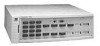
switching among all 24 Gigabit Ethernet ports. The system has the following ports (shown in Figure 1 on page 15): s 12 1000BASE-SX (MMF) ports with SC connectors s 12 GBIC ports that can accept 1000BASE-LX or 1000BASE-SX GBIC transceivers The system supports full-duplex mode on all Gigabit Ethernet - 3Com 3C94024 | Getting Started Guide - Page 12
the CoreBuilder 9400 in your network. Speeding Up Server Access To centralize your servers for easier service and support, use a configuration like must support a large number of clients that are distributed throughout the organization's campus. The clients are switched Fast Ethernet desktops. - 3Com 3C94024 | Getting Started Guide - Page 13
® 9400 system for management access LEDs Provide information about the system and each port ® R 3C94024 TX 1 RX 1000BASE SX TX 2 RX 1000BASE SX TX 3 RX PCKT STAT 10BASE TX STATUS PACKET SERVICE CONSOLE FAULT POWER 1000BASE (GBIC) TX 4 RX TX 7 RX TX 5 RX 1000BASE SX TX 6 RX TX 8 RX - 3Com 3C94024 | Getting Started Guide - Page 14
14 CHAPTER 1: SYSTEM AND SETUP OVERVIEW System Overview - Back Panel Figure 2 Back Panel of the CoreBuilder 9400 System Power supply latch DC OK ! Power Supply No. 2 DC OK ! Power Supply No. 1 - 3Com 3C94024 | Getting Started Guide - Page 15
34 35 36 Stat 7x 12x 19x 24x 31x 36x SuperStack II Switch 3900 1000 Base - LX 1000 Base - SX TX 1 RX TX 2 RX TX Switch 9300 To other Switch 3900s R 3C94024 TX 1 RX 1000BASE SX TX 2 RX 1000BASE SX TX 3 RX PCKT STAT 10BASE TX STATUS PACKET RESET CONSOLE FAULT POWER 1000BASE (GBIC - 3Com 3C94024 | Getting Started Guide - Page 16
16 CHAPTER 1: SYSTEM AND SETUP OVERVIEW - 3Com 3C94024 | Getting Started Guide - Page 17
the system in a distribution rack Installing the System on a Table Top To install the CoreBuilder 9400 system on a table top, follow these instructions: 1 See Appendix C for site requirements. 2 Turn the system on its side. 3 Remove the protective covering from the rubber feet and place one - 3Com 3C94024 | Getting Started Guide - Page 18
other bracket to the other side. See Figure 4. Figure 4 Installing System Mounting Brackets Mounting screws Mounting bracket R 3C94024 1000BASE SX TX 1 RX TX 2 RX TX 1000BASE SX TX 4 RX TX 5 RX TX 1000BASE SX You are now ready to cable the system. For cabling instructions, see Chapter 3. - 3Com 3C94024 | Getting Started Guide - Page 19
to the network at this point. See Chapter 4 to start your system before you cable it. Overview of Cabling The CoreBuilder 9400 system is a Gigabit Ethernet switch with this fixed configuration: s Twelve 1000BASE-SX ports s Twelve 1000BASE GBIC ports (LX or SX transceivers) Fiber Safety Precautions - 3Com 3C94024 | Getting Started Guide - Page 20
Implementation Guide for your system. Guidelines for Gigabit Ethernet Cabling For all Gigabit Ethernet cabling, keep the ports and connectors free of dust. See "Cleaning Dirty Fiber Optic Ports and Connectors" on page 40 for details. Recommended Distances for 1000BASE-SX Ports or Transceivers When - 3Com 3C94024 | Getting Started Guide - Page 21
4. When you cable GBIC transceivers, notice that the SC Receive (RX) port is on the left and the SC Transmit (TX) port is on the right. See Figure 9. Cabling Gigabit Ethernet Ports 21 Figure 5 shows cabling for the 1000BASE-SX ports. Figure 5 Cabling the 1000BASE-SX Port R 3C94024 1000BASE SX - 3Com 3C94024 | Getting Started Guide - Page 22
one of these transceivers: s 1000BASE-SX GBIC - Use this transceiver to connect the GBIC port directly to multimode fiber-optic cable. For instructions, see the procedure in this section. s 1000BASE-LX GBIC - Use this transceiver to connect the GBIC port directly to single-mode fiber-optic cable or - 3Com 3C94024 | Getting Started Guide - Page 23
fiber optic network cable into the duplex SC port on the GBIC transceiver, as shown in Figure 8. If you are using an SX transceiver, the fiber optic cable must support multimode transmission. If you are using an LX transceiver, the fiber optic cable must support single-mode transmission or multimode - 3Com 3C94024 | Getting Started Guide - Page 24
6 for additional GBIC ports. Connecting the LX Transceiver to MMF The LX transceiver supports a connection to multimode fiber using a conditioned launch cable. The conditioned launch cable consists of an offset mechanism on the transmit side of the cable that aligns the single-mode laser launch - 3Com 3C94024 | Getting Started Guide - Page 25
21 22 STATUS green = enabled, link OK flashing green = disabled, link OK off = link fail PCKT STAT 17 18 PCKT STAT 23 24 To network cable A RX TX SC connector B A Offset A A = Multimode fiber B = Single-mode fiber 7 Repeat steps 1 through 6 for additional 1000BASE GBIC ports. - 3Com 3C94024 | Getting Started Guide - Page 26
Gigabit Ethernet port using Telnet. See the Command Reference Guide. To use the Administration Console to configure the system for management access through the Console port, see Chapter 5. Figure 10 Cabling the Console Port CONSOLE FAULT POWER 1000BASE (GBIC) 15 16 1000BASE (GBIC - 3Com 3C94024 | Getting Started Guide - Page 27
the 10BASE-TX cable to the workstation or to a different network connection. To configure your CoreBuilder 9400 to use out-of-band network management, see the Command Reference Guide. This port is not a switch port, that is, it carries no network traffic. It is a port for management purposes only. - 3Com 3C94024 | Getting Started Guide - Page 28
Figure 11 Cabling the Out-of-Band Management Port Out-of-band management port 10BASE TX STATUS PACKET T CONSOLE FAULT POWER 1000BASE (GBIC) 14 15 16 1000BASE (GBIC) 20 21 22 STATUS green = enabled, link OK flashing green = disabled, link OK off = link fail PCKT STAT 17 18 PCKT - 3Com 3C94024 | Getting Started Guide - Page 29
instructions for the CoreBuilder® 9400 system s A description of "Power-up Diagnostics" s A list of "System Checks" after power up For information on troubleshooting , or a PC that has terminal emulation to the system's Console port. 1 Verify that the power outlet is near the system and easily - 3Com 3C94024 | Getting Started Guide - Page 30
to the network. If any component fails during power-up diagnostics, the system fails to power up. During power up, the system and port status LEDs Chapter 6 for troubleshooting information. Gigabit Ethernet Port Diagnostics This section summarizes the information displayed by the port LEDs. Packet - 3Com 3C94024 | Getting Started Guide - Page 31
Description If there is a problem during power-up, the messages are displayed in the Administration Console connection through the Console port. When the power-up diagnostics . To configure your system for your particular networking environment (including setting up SNMP), you must first establish management - 3Com 3C94024 | Getting Started Guide - Page 32
32 CHAPTER 4: SYSTEM POWER UP - 3Com 3C94024 | Getting Started Guide - Page 33
your system, follow the configuration instructions for your preferred type of Ethernet ports through the IP network protocol. For more detailed information, see the Command Reference Guide. For more complete network management, use an external SNMP-based management application such as 3Com - 3Com 3C94024 | Getting Started Guide - Page 34
manage the system, not for switching network traffic. Managing your system out-of-band conserves all available bandwidth for the Gigabit Ethernet ports. Also, if network problems exist, you can manage the system from a different network. See the Implementation Guide for more information on in-band - 3Com 3C94024 | Getting Started Guide - Page 35
management - Administer system management interface ethernet - Administer Ethernet ports bridge - Administer bridging/VLANs . Otherwise, press Return. 3 Enter baudRate. 4 Enter 9600 for the Console port. The system supports these baud settings: 19200, 9600, 4800, 2400, and 1200. The system - 3Com 3C94024 | Getting Started Guide - Page 36
the network instructions on assigning interface parameters, see the Command Reference Guide port. 3 Enter the subnet mask of the subnetwork to which the interface is to be connected. Press Return to accept the default subnet mask. 4 Enter the interface type: system For more detailed instructions - 3Com 3C94024 | Getting Started Guide - Page 37
covers: s Getting Additional Help s Diagnosing Problems s Cleaning Dirty Fiber Optic Ports and Connectors Getting Additional Help If you experience system problems that are not addressed in this chapter, contact your network supplier or 3Com Technical Support. Before you call, gather the following - 3Com 3C94024 | Getting Started Guide - Page 38
. 3 Try another power cable. 4 If the system still does not operate, contact your network supplier or 3Com Technical Support. Table 8 Troubleshooting Abnormal System LED Activity LED Status Possible Sources of the Problem Steps to Take Fault LED blinks yellow. Diagnostic software is not running - 3Com 3C94024 | Getting Started Guide - Page 39
the fiber optic ports and connectors. See next section. dirty. When the problem is corrected, the LED lights green. s If a GBIC port is affected, the transceiver may not be properly seated or is defective. If the LED still does not light, contact your network supplier or 3Com Technical Support. - 3Com 3C94024 | Getting Started Guide - Page 40
40 CHAPTER 6: TROUBLESHOOTING THE SYSTEM Cleaning Dirty Fiber Optic Ports and Connectors Fiber optic transceivers are sensitive optical devices. Handle them carefully. If dirt collects on a fiber optic lens, the associated LED may not light. You may also notice degradation in port performance, - 3Com 3C94024 | Getting Started Guide - Page 41
100003 for indirect connection to the public telecommunication network. IEC 950 Electromagnetic Emissions Heat Dissipation Meets FCC Supply Receptacles AC Line Frequency Input Voltage Options Current Rating 15 ampere service receptacles, type N5/15 or NEMA 5-15R (United States and Canada - 3Com 3C94024 | Getting Started Guide - Page 42
s Ethernet MIB (RFC 1284) s Bridge MIB (RFC 1286) Software Installation tftp (RFC 959) Terminal Emulation s telnet (RFC 854) s rlogin (RFC 1282) Protocols Used for Administration s UDP (RFC 768) s IP (RFC 791) s ICMP (RFC 792) s TCP (RFC 793) s ARP (RFC 826) s STP ((IEEE 802.1d)) s Flow control - 3Com 3C94024 | Getting Started Guide - Page 43
if you have not had the proper training from 3Com. For training information, call 1-800-NET-3COM or see the numbers for your country in Appendix Supply Assembly Removal and Replacement The CoreBuilder 9400 system operates using a single power supply assembly. You can add a second power supply to the - 3Com 3C94024 | Getting Started Guide - Page 44
44 APPENDIX B: FIELD-REPLACEABLE UNITS 4 Grasp the handle of the new power supply and gently slide it into the chassis. 5 To seat the power supply, ensure that all connectors are aligned. Then push the power supply inward until the connectors engage and latch. The latch should slide up. You feel a - 3Com 3C94024 | Getting Started Guide - Page 45
which contains two 12-volt DC fans. The fans are thermally controlled, which means that they run at slower speeds when the system that the connectors are properly aligned. Figure 14 Removing and Replacing the Fan Trays 3C94024 TX 1 RX 1000BASE SX TX 2 RX 1000BASE SX TX 3 RX PCKT STAT - 3Com 3C94024 | Getting Started Guide - Page 46
46 APPENDIX B: FIELD-REPLACEABLE UNITS - 3Com 3C94024 | Getting Started Guide - Page 47
plan at your facility probably covers most wiring closet concerns. 3Com also recommends that you check these items: s Verify that your codes. s Be sure that your system is easily accessible for installation and service. s Provide adequate overhead lighting for easy maintenance. s Be sure that all - 3Com 3C94024 | Getting Started Guide - Page 48
plan to have two or more CoreBuilder 9400 systems in a single wiring closet. s To prevent overheating during nonbusiness hours, guard kit, contact your sales representative. Space Requirements for the Rack Provide enough space in front of and behind the system so that you can service it easily. Allow - 3Com 3C94024 | Getting Started Guide - Page 49
Service Standard 297: Dimensions of Panels and Racks. In addition, 3Com recommends that your distribution racks meet these requirements: s Use distribution rack to avoid making it top heavy. s Use a rack that supports approximately 272 kg (600 lb) s Use a rack that has adequate electrical - 3Com 3C94024 | Getting Started Guide - Page 50
50 APPENDIX C: SITE REQUIREMENTS AND SAFETY CODES Figure 16 Recommended Rack Styles Building and Electrical Codes Follow all appropriate building codes and authorities on electrical codes when planning your site and installing your cable for the CoreBuilder 9400 system. Specific building and - 3Com 3C94024 | Getting Started Guide - Page 51
their own laws, ordinances, and codes on wiring specifications. The NEC Classification is published by: National Fire Protection Association (NFPA) 1 Batterymarch Park P.O. Box 9101 Quincy MA 02269-9109 USA www.nfpa.org s Underwriters' Laboratories (UL) Listing - An independent research and testing - 3Com 3C94024 | Getting Started Guide - Page 52
52 APPENDIX C: SITE REQUIREMENTS AND SAFETY CODES - 3Com 3C94024 | Getting Started Guide - Page 53
s 3Com Bulletin Board Service (3Com BBS) s 3Com FactsSM Automated Fax Service World Wide Web Site To access the latest networking information on the 3Com Corporation World Wide Web site enter this URL into your Internet browser: http://www.3com.com/ This service provides access to online support - 3Com 3C94024 | Getting Started Guide - Page 54
ISDN, call the following number: 1 847 262 6000 3Com Facts Automated Fax Service The 3Com Facts automated fax service provides technical articles, diagrams, and troubleshooting instructions on 3Com products 24 hours a day, 7 days a week. Call 3Com Facts using your Touch-Tone telephone: 1 408 727 - 3Com 3C94024 | Getting Started Guide - Page 55
If you are unable to obtain assistance from the 3Com online technical resources or from your network supplier, 3Com offers technical telephone support services. To find out more about your support options, call the 3Com technical telephone support phone number at the location nearest you. When you - 3Com 3C94024 | Getting Started Guide - Page 56
Here is a list of worldwide technical telephone support numbers: Country Asia Pacific Rim Australia Hong Kong India Indonesia Japan Malaysia New Zealand Pakistan 800 666 5065 800 666 5065 AT&T +800 666 5065 North America 1 800 NET 3Com (1 800 638 3266) Enterprise Customers: 1 800 876-3266 - 3Com 3C94024 | Getting Started Guide - Page 57
Returning Products for Repair 57 Returning Products for Repair Before you send a product directly to 3Com for repair, you must first obtain an authorization number. Products sent to 3Com without authorization numbers will be returned to the sender unopened, at the sender's expense. To obtain an - 3Com 3C94024 | Getting Started Guide - Page 58
58 APPENDIX D: TECHNICAL SUPPORT - 3Com 3C94024 | Getting Started Guide - Page 59
LEDs 30, 39 Ethernet Pckt LED troubleshooting 39 Ethernet Stat LED troubleshooting 39 F fan tray removal and replacement 45 Fault LED 30 troubleshooting 38 fault tolerance 12 fax service (3Com Facts) 54 feedback on documentation 10 fiber optic cables cleaning 40 fiber optic port safety 19 field - 3Com 3C94024 | Getting Started Guide - Page 60
60 INDEX G GBIC transceivers 22 Gigabit Ethernet cabling services 53 out-of-band management port cabling 27 setting IP parameters 36 P pin assignments Console port 27 port, out-of-band management 27 ports cleaning 40 fiber optic LED safety safety 19 problems 37 status 30 power cord, troubleshooting - 3Com 3C94024 | Getting Started Guide - Page 61
T table-top installation 17 technical support 3Com URL 53 bulletin board service 54 fax service 54 network suppliers 55 product repair 57 temperature specifications 41 transceiver Gigabit Interface Converter (GBIC) 22 troubleshooting LED activity 38 power failures 38 power-up system checks 30 - 3Com 3C94024 | Getting Started Guide - Page 62
62 INDEX - 3Com 3C94024 | Getting Started Guide - Page 63
3Com Corporation LIMITED WARRANTY CoreBuilder® 9400 High-Availability Switch HARDWARE 3Com warrants to the end user ("Customer") that this hardware product will be free from defects in workmanship and materials, under normal use and service, for one (1) year from the date of purchase from 3Com or - 3Com 3C94024 | Getting Started Guide - Page 64
. INCLUDED SERVICES: Telephone Support, with coverage for basic troubleshooting only, will be provided for ninety (90) days from the date of purchase, on a commercially reasonable efforts basis. Please refer to the Technical Support appendix in the Getting Started Guide for telephone numbers. 3Com
-
 1
1 -
 2
2 -
 3
3 -
 4
4 -
 5
5 -
 6
6 -
 7
7 -
8
-
9
-
10
-
11
-
12
-
13
-
14
-
15
-
16
-
17
-
18
-
19
-
20
-
21
-
22
-
23
-
24
-
25
-
26
-
27
-
28
-
29
-
30
-
31
-
32
-
33
-
34
-
35
-
36
-
37
-
38
-
39
-
40
-
41
-
42
-
43
-
44
-
45
-
46
-
47
-
48
-
49
-
50
-
51
-
52
-
53
-
54
-
55
-
56
-
57
-
58
-
59
-
60
-
61
-
62
-
63
-
64
 |
 |

®
CoreBuilder
®
9400
Getting Started Guide
Part No. 10013143
Published August 1999