3Com 3C94024 Getting Started Guide - Page 25
extension to the multimode network cable., If necessary, use fiber-optic couplers to connect
 |
UPC - 662705154404
View all 3Com 3C94024 manuals
Add to My Manuals
Save this manual to your list of manuals |
Page 25 highlights
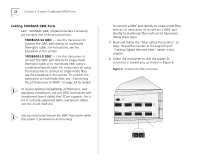
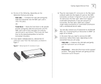
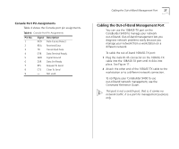
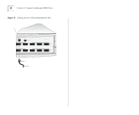
Cabling Gigabit Ethernet Ports 25 When you cable GBIC transceivers, note that the SC Receive (RX) port is on the left and the SC Transmit (TX) port is on the right. See Figure 9. 4 Insert the SC connectors on the conditioned launch cable into the transceiver as shown in Figure 9, ensuring that you: s Insert the SC connector on the multimode Receive (RX) side of the conditioned launch cable into the RX port on the transceiver. s Insert the SC connector on the single-mode Transmit (TX) side of the conditioned launch cable into the TX port on the transceiver. You can think of the conditioned launch cable as an extension to the multimode network cable. 5 Attach the other end of the conditioned launch cable to the multimode network cable, ensuring that you: s Connect the multimode RX side of the conditioned launch cable to the RX side of the network cable. s Connect the multimode TX side of the conditioned launch cable to the TX side of the network cable. If necessary, use fiber-optic couplers to connect the male SC connectors on the multimode end of the conditioned launch cable to the multimode network cable. 6 Attach the other end of the network fiber-optic cable to the network device that you want to connect. Figure 9 Connecting Using a Conditioned Launch Cable 0BASE TX US PACKET CONSOLE FAULT POWER 1000BASE (GBIC) 14 15 16 1000BASE (GBIC) 20 21 22 STATUS green = enabled, link OK flashing green = disabled, link OK off = link fail PCKT STAT 17 18 PCKT STAT 23 24 To network cable A RX TX SC connector B A Offset A A = Multimode fiber B = Single-mode fiber 7 Repeat steps 1 through 6 for additional 1000BASE GBIC ports.
-
 1
1 -
2
-
3
-
4
-
5
-
6
-
7
-
8
-
9
-
10
-
11
-
12
-
13
-
14
-
15
-
16
-
17
-
18
-
19
-
 20
20 -
 21
21 -
 22
22 -
 23
23 -
 24
24 -
 25
25 -
 26
26 -
 27
27 -
 28
28 -
 29
29 -
 30
30 -
31
-
32
-
33
-
34
-
35
-
36
-
37
-
38
-
39
-
40
-
41
-
42
-
43
-
44
-
45
-
46
-
47
-
48
-
49
-
50
-
51
-
52
-
53
-
54
-
55
-
56
-
57
-
58
-
59
-
60
-
61
-
62
-
63
-
64
 |
 |