Aastra OpenCom 510 User Guide
Aastra OpenCom 510 Manual
 |
View all Aastra OpenCom 510 manuals
Add to My Manuals
Save this manual to your list of manuals |
Aastra OpenCom 510 manual content summary:
- Aastra OpenCom 510 | User Guide - Page 1
OpenCom 510 Mounting and Commissioning User Guide - Aastra OpenCom 510 | User Guide - Page 2
with regard to quality and design. The following operating instructions will assist you in using your OpenCom 510 and answer most of the questions that may arise. If you require further technical support or information about other Aastra DeTeWe products, please refer to our website at www - Aastra OpenCom 510 | User Guide - Page 3
Internet Functions 17 3. Preliminary Information 19 3.1 Construction of the OpenCom 510 19 3.2 Scope of Delivery 19 3.3 Declarations of Conformity 20 4. Installation 21 4.1 Safety Precautions 21 4.1.1 General Instructions 21 4.1.2 Notes on the Mains Supply 22 4.1.3 Notes - Aastra OpenCom 510 | User Guide - Page 4
Variants 46 5.4 a/b Ports 48 5.4.1 Terminals Connected to a/b Ports 48 5.4.2 Technical Information 50 5.5 LAN Port 51 5.5.1 DSL Port 51 5.5.2 Service PC 52 5.6 COM Port 52 6. Accessories and Adapters (OpenPhone 61, 63, 65 54 6.1 Upn Adapter 54 6.2 a/b Adapter 54 - Aastra OpenCom 510 | User Guide - Page 5
76 MX+S01-8 80 MS+UPN1-8 83 MS+UPN2-8 85 MS+A1-8 87 MS+A1-4 89 Configuration 91 Brief Guide to Initial Configuration 92 Configuring the OpenCom 510 94 Preparing the Configuration 94 Starting the Web Console 94 Loading the Online Help 96 Finishing the Configuration 96 Preconfiguration 96 - Aastra OpenCom 510 | User Guide - Page 6
.5 11.5.1 11.5.2 12. 12.1 12.1.1 12.1.2 Internet Access 106 RAS Access 107 OpenCom 510 in a LAN with an IP-enabled Server 108 DNS Name Resolution 108 Internet Access 109 120 Call set-up 120 Useful services 121 Media Gateway (MGW 121 MG+ETH1-1 122 SIP Telephony 124 VoIP System Telephones - Aastra OpenCom 510 | User Guide - Page 7
154 Connection via an Active Transmission System 155 Connection via the Public Network 155 Connection via Q.SIG.IP 156 Configuration 157 Trunk groups 157 Routes 157 Numbering 158 Technical Details 160 Team Functions 161 Introduction 161 Explanation of Keys 161 Team Configuration 163 - Aastra OpenCom 510 | User Guide - Page 8
Configuring and Managing Companies 179 Assigning Users 179 Assigning Trunk Groups/SIP Accounts 180 Allocating Routing Codes 180 Configuring the Company 182 Configuring the PC Software 183 PC Offline Configuration 183 Setting up TAPI 185 Setting up NET CAPI 187 Using the Systray Display 188 - Aastra OpenCom 510 | User Guide - Page 9
19. Configuration Guide 194 19.1 Overview 195 19.2 PBX Ports 196 19.3 LAN 197 19.4 WAN Settings 198 19.5 RAS Settings 199 19.6 Branch Settings 200 19.7 E-mail - Aastra OpenCom 510 | User Guide - Page 10
8 - Aastra OpenCom 510 | User Guide - Page 11
with structured cabling. All connections to a structured cabling patch panel can be made with standard patch cables. The OpenCom 510 supports the following communications applications: ■ Telephony with system telephones, ISDN telephones and analogue terminals, Internet/intranet data communication - Aastra OpenCom 510 | User Guide - Page 12
510 firmware is designed for a maximum of 600 users. For information on system limitations, refer to Technical Data starting on page 211. The following can be connected to the OpenCom 510: ■ Euro ISDN terminals ■ DeTeWe system telephones ■ OpenPhone 52 ISDN telephones (to the Upn port) ■ DeTeWe - Aastra OpenCom 510 | User Guide - Page 13
which is connected to the system. The OpenCom 510 can be pre-configured at the service centre and remote-configured for service purposes. A COM port can be used their PCs without having to install a special TAPI driver. Further Telephony Features The OpenCom 510 can be used to run digital voicebox - Aastra OpenCom 510 | User Guide - Page 14
LAN can be connected by means of the Ethernet port. If Internet access is already available from an Internet service provider, the OpenCom 510 can be configured accordingly. The OpenCom 510 can also be used for IP configuration if there is no IP-capable client network. An integrated DHCP server - Aastra OpenCom 510 | User Guide - Page 15
"OpenPhone 27" user guide. For information on configuring the OpenPhone 27 data interface, please refer to the OpenCom 510 online help. E-Mail The OpenCom 510 offers an integrated e-mail function that supports the POP3, APOP or IMAP4 protocols used to query an Internet service provider for incoming - Aastra OpenCom 510 | User Guide - Page 16
, are not able to make external calls, and have only restricted use of the terminal functions of the OpenCom 510. The "Standard" user group, because of its default settings, is well suited as a starting point for the creation of user groups for normal users of the system (e.g. the staff members of - Aastra OpenCom 510 | User Guide - Page 17
Factory Settings Authorisations Note: When the OpenCom 510 is first put into operation, all connected terminals are in the "Administrators" group until a user logs on to the web console. All terminals are then - Aastra OpenCom 510 | User Guide - Page 18
by any factor. There are no preset basic amounts for the charging of calls. ■ Speed dialling is possible, provided it has been configured in the OpenCom 510 central telephone book. ■ Keypad dialling is possible. 16 - Aastra OpenCom 510 | User Guide - Page 19
and analysed. ■ Users can use the OpenCTI 50 to send short messages to other users. ■ Every user can change the configuration of the OpenCom 510. ■ Every user can create a personal telephone book and edit entries in the central telephone book. ■ Every user can read out the charges. ■ Applications - Aastra OpenCom 510 | User Guide - Page 20
Factory Settings Internet Functions ■ Host name: host ■ IP address: 192.168.99.254 ■ Network mask: 255.255.255.0 The following addresses are transmitted to the LAN's client PCs using DHCP or PPP: ■ Gateway address: 192.168.99.254 ■ Domain name: domain ■ Domain name server: 192.168.99.254 ■ PPP - Aastra OpenCom 510 | User Guide - Page 21
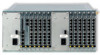
the sockets for the control module and the interface cards; it supplies the modules/cards with the required power and system signals. The OpenCom 510 comes fully assembled. By contrast with other systems, you will not need to assemble the frame and backplane yourself. A power supply unit and - Aastra OpenCom 510 | User Guide - Page 22
covering unused slots ■ 1 set of short user guides ■ 1 CD 3.3 Declarations of Conformity The communications systems of the OpenCom 100 product family comply with the requirements of EU directive 99/5/EC. The declarations of conformity can be found on the Internet at http://www.aastra-detewe.de. 20 - Aastra OpenCom 510 | User Guide - Page 23
of approval. 4.1.1 General Instructions Please note: This product may be installed and serviced by qualified personnel only. OpenCom 510 components for transport or storage. CAUTION! Static charge can damage the OpenCom 510. Before and during work on the electrical components of the OpenCom 510 - Aastra OpenCom 510 | User Guide - Page 24
units must be plugged into its own mains socket. It is not permissible to use multiway mains strips to connect more than one OpenCom 510 power supply unit or a OpenCom 510 and other devices to the same mains supply together. The mains cables of the MPS+1-AC power supply units must have ferrite rings - Aastra OpenCom 510 | User Guide - Page 25
's wiring system) by means of a solid or stranded wire of at least 2,5 mm2 (yellow/green). ø 2,5 mm2 ø 2,5 mm2 OpenCom 510: Earthing arrangement The metal screens of the subscriber and trunk cables must be connected to the circuit common in the distributor or the patch field. The protective earth - Aastra OpenCom 510 | User Guide - Page 26
in the scope of delivery). 4.1.5 Notes on Installing Terminals Only devices that supply safety extra-low voltage (SELV) may be connected to the OpenCom 510. Proper use of standard terminals will satisfy this requirement. The analogue interfaces may only be used to connect terminals that meet the - Aastra OpenCom 510 | User Guide - Page 27
19" cabinet, ensure that the air intake temperature for the OpenCom 510 does not exceed +40 °C. The OpenCom 510 may also be connected to an IT system. 4.3 Installation in a 19" Rack 1 C 2 C B A OpenCom 510: 1-12 frame mounting points The OpenCom 510 is designed to be installed in 19" racks only - Aastra OpenCom 510 | User Guide - Page 28
the 19" rack C Left and right screw points for earthing wrist strap or circuit common connection between 1-12 frame and 19" rack Note: If the OpenCom 510 is to be used as a wall-mounted instead of a floor-standing system, it must be installed in a standard-type wall-mounted enclosure using 19 - Aastra OpenCom 510 | User Guide - Page 29
Installation Installing Modules 4.4.1 Slots The OpenCom 510 1-12 frame can house up to: ■ 2 power supply units ■ 1 control module ■ 12 interface cards (trunk or subscriber modules) split into 2 separate groups. The following slots are provided for installing these modules: Legend A Slot for group - Aastra OpenCom 510 | User Guide - Page 30
installing the central control module or a power supply unit. If you unplug the mains cable of the group 2 (B) power supply unit, the OpenCom 510 will still be operational! However, only the modules supplied by the group 1 (A) power supply unit, i.e. the central control module and the interface - Aastra OpenCom 510 | User Guide - Page 31
comes with the central control module installed. Should you need to exchange the central control module, proceed as follows: 1. Shut down the OpenCom 510. To do so, first restart the system by - entering the code procedure H*185 (system PIN) # on a connected telephone, or - clicking on Restart in - Aastra OpenCom 510 | User Guide - Page 32
the IP settings. For further information on MAC addresses, refer to the online help. Explanatory Note on Shutting Down the System If the OpenCom 510 is disconnected from the mains supply, its main memory is deleted. The main memory stores the current configuration data, which are regularly copied - Aastra OpenCom 510 | User Guide - Page 33
push the interface card into the corresponding slot. The printing on the front of the module should be at the top (see illustration in previous instruction). 31 - Aastra OpenCom 510 | User Guide - Page 34
Status of the Interface Cards via the Web Console You can also check the status of the interface cards via the Web console of the OpenCom 510. 1. Open the PBX Configuration: Ports: Slots page in the Configurator. 2. In the Status table row, check whether a green tick is displayed for the newly - Aastra OpenCom 510 | User Guide - Page 35
in in slots 7 - 12. If you want to deinstall the second power supply unit or exchange a defective one, proceed as follows: 1. Shut down the OpenCom 510. To do so, first restart the system by - entering the code procedure H*185 (system PIN) # on a connected telephone, or - clicking on Restart in the - Aastra OpenCom 510 | User Guide - Page 36
. Observe the regulations regarding electrostatically sensitive components. 5. Carefully push the power supply unit into the corresponding slot (see also the illustration OpenCom 510: 1-12 frame slots on page 26). Seen from the front, the mains inlet socket should be on the bottom right. Ensure - Aastra OpenCom 510 | User Guide - Page 37
you need to exchange the backplane, proceed as follows: DANGER! Hazardous voltages inside the device! 1. Unplug all of the mains cables of the OpenCom 510 to disconnect the system from the mains supply. Refer to Notes on Disconnecting the Mains Supply starting on page 28. 2. Uninstall all modules - Aastra OpenCom 510 | User Guide - Page 38
needs to be reactivated using new activation keys. Contact your dealer or DeTeWe distributor. 9. The new keys will be generated using the backplane serial PARK of a DECT system. If you are using a DECT system with the OpenCom 510, you will need to reenter the PARK. 11.You can determine the new PARK - Aastra OpenCom 510 | User Guide - Page 39
configurations, the OpenCom 510 provides an emergency service feature: In the default: off ). ■ Port S01 must be connected to an NTBA (multi-terminal access) and configured as an external connection. ■ Port S08 must be configured as an internal connection. An ISDN telephone with emergency service - Aastra OpenCom 510 | User Guide - Page 40
Installation Power Failure Note: Emergency service is not possible with system access configurations. Testing the Power Failure Circuit You can test the configuration as follows: 1. Disconnect the OpenCom 510 from the mains supply (see instructions in Installing the Central Control Module starting - Aastra OpenCom 510 | User Guide - Page 41
Interfaces and Connectible Terminals 5. Interfaces and Connectible Terminals Overview 5.1 Overview The OpenCom 510 interfaces have been implemented as RJ45 sockets on the front of the interface cards and the central control module. No special proprietary cables are required. - Aastra OpenCom 510 | User Guide - Page 42
Interfaces and Connectible Terminals S0 Ports Overview: Interfaces and Connectible Terminals Interface Terminals/Systems Page S0 (internal) ISDN terminals (DSS1 protocol): 40 telephones, fax machines, base stations and handsets, ISDN cards for PCs Upn Digital terminals (ISDN terminals, - Aastra OpenCom 510 | User Guide - Page 43
). The DIP switches activate the required terminating resistors for the S0 buses (100 ohms per S0 bus). In the default setting, all terminating resistors are activated (Default: on). ON 12 MX+S01-8: Location of DIP switches S1 to S16 Note: The following configuration information applies to - Aastra OpenCom 510 | User Guide - Page 44
network termination for basic access (NTBA) with an externally switched S0 port; therefore, all terminating resistors of the interface card are activated in the default setting. ON 12 OpenCom 510 TR IAE IAE MX+S01-8: Terminating resistors activated One end of the S0 bus is terminated by the - Aastra OpenCom 510 | User Guide - Page 45
the instructions in Installing Interface Cards starting on page 31. 2. The DIP switches are protected by a plastic foil. Use a pointed tool such as a screwdriver to slide the DIP switches down (see arrow in the illustration MX+S01-8: Terminating resistors deactivated). ON 12 OpenCom 510 TR - Aastra OpenCom 510 | User Guide - Page 46
refer to the illustration Wiring for direct connection on page 44. If the terminal did not come with a suitable ISDN cable, contact your dealer or DeTeWe distributor. The length of an internal S0 bus cable must not exceed 150 m. Each internal S0 bus has a power feed of approx. 3 W. The feed voltage - Aastra OpenCom 510 | User Guide - Page 47
of a Upn adapter, which enables you to connect two OpenPhones to one Upn port. For further information, refer to the "OpenPhone 61, 63, 65" user guide. The RFP 22 DECT base station can be used to connect the OpenPhone 26 and OpenPhone 27 DECT handsets. The OpenPhone 27 has an USB - Aastra OpenCom 510 | User Guide - Page 48
Interfaces and Connectible Terminals Upn Ports 5.3.3 DECT Base Station Connection Variants A DECT base station can be connected to either one or two Upn interfaces: ■ If the DECT base station is connected to one Upn interface, four simultaneous calls or connections can be made through the handsets - Aastra OpenCom 510 | User Guide - Page 49
be connected here; use only the first Upn port in this configuration. Setting DIP Switches 1. Remove the interface card by following the instructions in Installing Interface Cards starting on page 31. 2. The DIP switches are protected by a plastic foil. Use a pointed tool such as a screwdriver - Aastra OpenCom 510 | User Guide - Page 50
Telephones If analogue telephones are to be connected, we recommend devices that support dual-tone multi-frequency (DTMF) dialling as it is not possible to use the additional features of the OpenCom 510 with pulse dialling telephones. Modems The maximum transmission rate for analogue modems - Aastra OpenCom 510 | User Guide - Page 51
cause irreparable damage to the OpenCom 510! Voice Mail If you option, if you want to use the actor port of the OpenCom 510 instead of the "DoorLine" relay. The "DoorLine" actor can be only one "DoorLine" with the OpenCom 510. For details on installing and configuring the "DoorLine" intercom system - Aastra OpenCom 510 | User Guide - Page 52
Interfaces and Connectible Terminals a/b Ports The intercom system should be installed by qualified personnel only as sensor/ actor contacts will need to be connected to the "DoorLine" module. 5.4.2 Technical Information The a/b ports have been implemented as RJ45 sockets. Each of the devices - Aastra OpenCom 510 | User Guide - Page 53
(Local Area Network) with the use of a 10-Mbit hub or switch. In such a configuration, the OpenCom 510 can, for example, act as an IP router for establishing Internet connections. The Ethernet interface supports transmission rates of 10 Mbits/s and 100 Mbits/s in half duplex or full duplex mode. The - Aastra OpenCom 510 | User Guide - Page 54
Ethernet interface can also be used to connect a service PC using a crossed Ethernet cable. 5.6 COM special 10-pin cable is required for connecting apparatus to the V.24-1 interface. Contact your DeTeWe distributor or local retailer if you want to purchase one of these cables. Pin Assignment 1 - Aastra OpenCom 510 | User Guide - Page 55
Interfaces and Connectible Terminals Pin Number 8 9 10 Assignment DSR DCD Not used COM Port 53 - Aastra OpenCom 510 | User Guide - Page 56
for various adapters and other accessories. Further information on installing and operating these add-ons can be found in the "OpenPhone 61, 63, 65" user guide under "Add-ons (with & without an Adapter)". In the following you will find technical details on the add-ons and a list of compatible - Aastra OpenCom 510 | User Guide - Page 57
mm signal, relay contact 1 ates signal for starting and stopping 2 (peak): recording signal + recording. 3 (ring): relay contact 1 3 Not used on Round power - OpenCom 510 socket (4 mm) 4 Door display RJ-11 or 4, 5: relay contact 2 RJ-12 (6-pin 1, 2, 3, 6: NC Western socket) 55 - Aastra OpenCom 510 | User Guide - Page 58
3-in-1 (1866-00-04) Headset adapter cable: Second handset GN Netcom, QD cable (quick coupling), smooth, Mod 4 (8800-00-01) Siemens, L30351-F600-A366 Handset DeTeWe, OpenPhone 60 56 - Aastra OpenCom 510 | User Guide - Page 59
Accessories and Adapters (OpenPhone 61, 63, 65) Device Combinations The following devices are recommended: Type Manufacturer, Product Designation Microphone: Winfinity, 4511326 / H 282-18 Loudspeaker: Siemens, L30460-X1278-X Recording device: No recommendation 6.5 Device Combinations You - Aastra OpenCom 510 | User Guide - Page 60
Accessories and Adapters (OpenPhone 61, 63, 65) Device Combinations Configurations without Plug-in Power Supply (Range up to 500 m) The following table shows examples of equipment combinations for which the maximum power consumption of 2.4 W is not exceeded. Basic Unit: OpenPhone 63 Add-ons - Aastra OpenCom 510 | User Guide - Page 61
Accessories and Adapters (OpenPhone 61, 63, 65) Device Combinations Configurations without Plug-in Power Supply (Range 500 to 1000 m) The following table shows examples of equipment combinations for which the maximum power consumption of 2.2 W is not exceeded. Basic Unit OpenPhone 63 OpenPhone 65 - Aastra OpenCom 510 | User Guide - Page 62
Accessories and Adapters (OpenPhone 61, 63, 65) Device Combinations Basic Unit: OpenPhone 65 Add-ons: Second terminal (OpenPhone, OP) Up to 3 keypad modules Audio adapter Upn adapter and plug-in power supply OP 61 OP 63 without adapter OP 65 without adapter and with 1 keypad module ● ● - Aastra OpenCom 510 | User Guide - Page 63
Extensions and accessories for system telephones (OpenPhone 71, 73, 75) Power supply 7. Extensions and accessories for system telephones (OpenPhone 71, 73, 75) 7.1 Power supply unit The power supply unit 4516000 (in Britain operate only the AC adapter with the part no. 4516001)is required in the - Aastra OpenCom 510 | User Guide - Page 64
is assigned to each key The number of keypad extensions connected to a system telephone (up to three) can be set in the Configurator of the OpenCom 510's Web Console (in the menu PBX Configuration: Devices: System telephone or VoIP telephone). Here the keys can also be programmed as call keys or - Aastra OpenCom 510 | User Guide - Page 65
. Use discharging underlays or antistatic mats where possible. Please note: Never attach a keypad extension to a system telephone that is already connected to OpenCom 510. Pull the telephone plug out of the socket before screwing the keypad extension onto it. 1 2 2 This symbol on the system - Aastra OpenCom 510 | User Guide - Page 66
the underside of the system telephone. 3. Activate the headset on the system telephone in the menu "Telephone settings: Headset" (see also the system telephone's user guide). 64 - Aastra OpenCom 510 | User Guide - Page 67
for storing data. ■ Interface cards are used to connect the OpenCom 510 to the telecommunications network (or to another communications system) and the interface card's functions, it may also be referred to as a trunk module or as a subscriber module. For detailed information on installing modules, - Aastra OpenCom 510 | User Guide - Page 68
the module's type and function: Mx+y1-z Abbr. M x + y 1 z Meaning Module Indicates the module type as follows: C Control S Subscriber T Trunk X Subscriber/Trunk PS Power Supply Character used to divide the product name Indicates the interface type as follows: A Analogue interface - Aastra OpenCom 510 | User Guide - Page 69
following table provides an overview of modules available for the OpenCom 510: Name MPS+1-AC MC+1-3 MT+S2M1-1 MX+S01-8 trunk) or internal (subscriber) connections Subscriber module with eight Upn interfaces for connec- 83 ting digital terminals (ISDN terminals, system telephones); does not support - Aastra OpenCom 510 | User Guide - Page 70
Modules MX+S01-8 Overview of Available Modules S0 2 S0 1 Detail: Printing on the front of an MX+S01-8 interface card 68 - Aastra OpenCom 510 | User Guide - Page 71
Modules MPS+1-AC 8.3 MPS+1-AC Field of Application The MPS+1-AC power supply unit supplies power to the first six slots (1 to 6) of the OpenCom 510. It converts the (220 V/110 V) AC input voltage into DC voltage +3.3 V and -42 V. If the remaining slots (7 to 12) are to be used, a second MPS+1- - Aastra OpenCom 510 | User Guide - Page 72
Modules MPS+1-AC Input Voltage Rated voltage Voltage range Rated current Efficiency at rated load 230 V via standard IEC connector 95 V to 275 V 2.0 A at 115 V 1.0 A at 230 V 0.9 A at 275 V > 80 % +3.3 V Output Voltage Rated voltage Voltage range Rated current Current limitation Short-circuit - Aastra OpenCom 510 | User Guide - Page 73
Modules MPS+1-AC ■ Right: If the right LED is constantly lit up green, the output voltage is -42 V. The LEDs only indicate that the voltage is present. They do not say anything about the voltage quality. Operational Information The MPS+1-AC power supply unit will be ready for operation as soon as - Aastra OpenCom 510 | User Guide - Page 74
Modules 8.4 MC+1-3 MC+1-3 MC+1-3 V.24-2 V.24-1 Ethernet PCM MC+1-3: Front view Field of Application The MC+1-3 module is the central control module of the OpenCom 510. It can be installed in slot 0 only (at the left end in the 1-12 frame; see Slots starting on page 27). In addition to the - Aastra OpenCom 510 | User Guide - Page 75
plug-in card must not be exchanged by service personnel. In the event of a malfunction, card: the OpenCom 510 firmware, the system terminal DeTeWe distributor or local retailer if you want to purchase one of these cards. ■ The Ethernet port (10/100 Mbits/s) can be used to connect the OpenCom 510 - Aastra OpenCom 510 | User Guide - Page 76
(flickering is normal). Flashing green/yellow The system software (firmware) is starting up. Flashing yellow The booter is reloading. exchange the central control module, shut down the system first! The OpenCom 510 must be disconnected from the mains supply (see Installing the Central - Aastra OpenCom 510 | User Guide - Page 77
Modules ■ 6 DTMF transmitters ■ 10 DTMF receivers ■ 1 Music On Hold ■ 32 HDLC controllers for RAS, ISP and DECT data. MC+1-3 75 - Aastra OpenCom 510 | User Guide - Page 78
-1 MT+S2M1-1 -42V S2M MT+S2M1-1: Front view Field of Application The MT+S2M1-1 interface card provides one ISDN S2M interface for connecting the OpenCom 510 either to a primary rate access or to a second PBX (ISDN point-topoint connection). The MT+S2M1-1 interface card can be installed in any of - Aastra OpenCom 510 | User Guide - Page 79
Modules MT+S2M1-1 ■ A maximum of four MT+S2M1-1 interface cards can be configured in the entire system. ■ No settings need to be made on the MT+S2M1-1 interface card. ■ The MT+S2M1-1 interface card runs on software acquired from the system. After the card has been installed it will automatically - Aastra OpenCom 510 | User Guide - Page 80
Modules MT+S2M1-1 Pin Number 4 5 6 7 8 Assignment 0 V 0 V -42 V Not used Not used Indicators There are four LEDs on the front of the MT+S2M1-1 interface card. MT+S2M1-1 1 3 2 4 -42V S2M MT+S2M1-1: LEDs The LEDs indicate the following: LED 1: Constantly yellow LED 2: Constantly green - Aastra OpenCom 510 | User Guide - Page 81
Modules MT+S2M1-1 Constantly red LED 3: Constantly green LED 4: - New software is being loaded onto the interface card. If the LED lights up red for an extended period of time, there may be a fault. The interface card is providing the system clock signal (indicated only in the master system and - Aastra OpenCom 510 | User Guide - Page 82
OpenCom 510 (see Slots starting on page 27). Technical Information ■ The MX+S01-8 interface card can also be installed in a slave system. ■ DIP switches S1 to S16 can be used to activate a 100-ohm terminal resistor (default (internal) interfaces or as trunk (external) interfaces. For further - Aastra OpenCom 510 | User Guide - Page 83
the system clock signal (indicated only in the master system and only on an interface card). The interface card is running a combination of subscriber and trunk connections, i.e. both internal and external S0 interfaces have been configured. 81 - Aastra OpenCom 510 | User Guide - Page 84
Modules MX+S01-8 Operational Information The MX+S01-8 interface card can be exchanged during operation, i.e. without powering down the system. However, the slot must first be deactivated in the Configurator in the web console (see Installing Interface Cards starting on page 31). All three protocol - Aastra OpenCom 510 | User Guide - Page 85
is not possible to connect DECT base stations. The MS+UPN1-8 interface card can be installed in any of the slots (1 to 12) of the OpenCom 510 (see Slots starting on page 27). Technical Information ■ The MS+UPN1-8 interface card can also be installed in a slave system. ■ No settings need to be - Aastra OpenCom 510 | User Guide - Page 86
Modules MS+UPN1-8 1 3 2 4 MS+UPN1-8 UPN 2 UPN 1 MS+UPN1-8 The LEDs indicate the following: LED 1: Constantly yellow LED 2: Constantly green Flashing yellow Constantly red LED 3: - LED 4: - At least one connection established through the interface card is active. The interface card is - Aastra OpenCom 510 | User Guide - Page 87
for connecting system terminals and DECT base stations. The MS+UPN2-8 interface card can be installed in any of the slots (1 to 12) of the OpenCom 510 (see Slots starting on page 27). Technical Information ■ The MS+UPN2-8 interface card can also be installed in a slave system. ■ A maximum of 48 RFPs - Aastra OpenCom 510 | User Guide - Page 88
Modules MS+UPN2-8 1 3 2 4 MS+UPN2-8 UPN 2 UPN 1 MS+UPN2-8: LEDs The LEDs indicate the following: LED 1: Constantly yellow LED 2: Constantly green Flashing yellow Constantly red LED 3: - LED 4: - At least one connection established through the interface card is active. The interface card is - Aastra OpenCom 510 | User Guide - Page 89
can be installed in any of the slots (1 to 12) of the OpenCom 510 (see Slots starting on page 27). Technical Information ■ The MS+A1-8 interface card can also be installed in a slave system. ■ The MS+A1-8 interface card supports pulse dialling as well as dual-tone multifrequency (DTMF) dialling. The - Aastra OpenCom 510 | User Guide - Page 90
Modules MS+A1-8 1 3 2 4 MS+A1-8 a/b 2 a/b 1 MS+A1-8: LEDs The LEDs indicate the following: LED 1: Constantly yellow LED 2: Constantly green Flashing yellow Constantly red LED 3: - LED 4: - At least one connection established through the interface card is active. The interface card is - Aastra OpenCom 510 | User Guide - Page 91
analogue trunk lines. The MT+A1-4 interface card can be installed in any of the slots (1 to 12) of the OpenCom 510 (see Slots starting on page 27). Technical Information ■ The MT+A1-4 interface card can also be installed in a slave system. ■ The MT+A1-4 interface card supports pulse dialling - Aastra OpenCom 510 | User Guide - Page 92
Modules MT+A1-4 1 3 2 4 MS+A1-4 a/b 2 a/b 1 MT+A1-4: LEDs The LEDs indicate the following: LED 1: Constantly yellow LED 2: Constantly green Flashing yellow Constantly red LED 3: - LED 4: - At least one connection established through the interface card is active. The interface card is - Aastra OpenCom 510 | User Guide - Page 93
the Web console, you can: ■ perform the initial configuration of the OpenCom 510, ■ configure users of the OpenCom 510 and authorise them to use certain system services, ■ carry out further system maintenance, ■ use PC-supported telephony functions, ■ read out call charge information, ■ access the - Aastra OpenCom 510 | User Guide - Page 94
Configuration Brief Guide to Initial Configuration Note: In order to use all the new system software functions, we recommend that you download the latest software from our Web site at http://www.aastra-detewe.de. For the initial configuration you can connect the PC to the OpenCom 510 via the - Aastra OpenCom 510 | User Guide - Page 95
Configuration Brief Guide to Initial Configuration Setting the IP address in Windows XP Tip: To find out the IP address of the Web console, enter the code digit - Aastra OpenCom 510 | User Guide - Page 96
of the OpenCom 510) with their names, departments, and the internal call numbers you want to allocate to them ■ For Internet access: the Internet service provider access data. Data not available for initial configuration can be updated or corrected at a later date. Note: Use the Configuration Guide - Aastra OpenCom 510 | User Guide - Page 97
Configuration Configuring the OpenCom 510 OpenCom 510: log-on dialogue box 3. To commence configuration, you must first log on. For the initial configuration, enter your: - user name: "Administrator" - password: for the initial configuration, leave this box blank. 4. Confirm this by clicking on OK - Aastra OpenCom 510 | User Guide - Page 98
OpenCom 510 5. The software opens a dialogue for initial access. Determine an administrator password help from http://www.aastra-detewe.de/. 9.2.4 Finishing the OpenCom 510 can be prepared at your DeTeWe Customer Service Centre or by an authorised DeTeWe dealer. For this purpose, a OpenCom 510 - Aastra OpenCom 510 | User Guide - Page 99
type of the product family and firmware version release 7.0 or higher, has supported. You can find further information in the chapter PC Offline Configuration starting on page 183. 9.2.7 Remote Configuration The OpenCom 510 configuration can also be altered or updated remotely by a customer service - Aastra OpenCom 510 | User Guide - Page 100
OpenCom 510 Note: If you do not wish to let the customer service centre/ authorised dealer know the administrator password, you can define a temporary password OpenCom 510 and the software for the connected system terminals and base stations can also be installed (see the SYS Configuration: Firmware - Aastra OpenCom 510 | User Guide - Page 101
a user off: 1. The "Administrator" user logs on with the administration password. 2. They open the Configurator. A message shows which user is currently . 9.2.8 Codes for IP Configuration The IP configuration of the OpenCom 510 is performed on the Web console in the Configurator, in the - Aastra OpenCom 510 | User Guide - Page 102
backup. 9.2.10 Receiving System Messages as E-Mail Important events and errors are kept by the OpenCom 510 in an internal log book: the error store. To inform or alert the system administrators, Further, extra parameters (such as the port number when a trunk line drops out) are also provided. 100 - Aastra OpenCom 510 | User Guide - Page 103
PC, which accesses the Configurator (see the SYS Configuration: Firmware menu). For information on connecting a configuration PC, see Brief Guide to Initial Configuration on page 92. The terminal software is part of the OpenCom 510 software and is automatically loaded into the terminals via the - Aastra OpenCom 510 | User Guide - Page 104
directory called "Multimedia". The MoH file must be coded with 8000 Hz, 8 bit mono in accordance with CCITT, ALaw. This coding is required for the OpenCom 510 and can be set in the "Sound Recorder" when you save the file under Format (CCITT, A-Law) and Attributes (8000 Hz, 8 bit mono). The maximum - Aastra OpenCom 510 | User Guide - Page 105
which enables the integration of external staff in the LAN. In this chapter you will find several examples of configurations showing integration of the OpenCom 510 in a LAN. Which example applies to your situation depends on the size and properties of the existing or planned LAN infrastructure. Note - Aastra OpenCom 510 | User Guide - Page 106
TCP/IP In a single LAN it is possible to use various protocols for the transmission of data. The connection between a workstation computer and the OpenCom 510 runs via the IP protocol (also named TCP/IP) used on the Internet. IP can be used together with other protocols (e.g. NetBEUI, AppleTalk or - Aastra OpenCom 510 | User Guide - Page 107
does not fit the network mask, the connection is established via the default gateway. If a device knows several data routes to different intermediate stations, technical terms, refer to the Glossary on the CD supplied. 10.3 OpenCom 510 in a Serverless LAN In a peer-to-peer network, the workstations - Aastra OpenCom 510 | User Guide - Page 108
for such networks is used: 192.168.99.254 255.255.255.0 192.168.99.254 192.168.99.254 OpenCom 510 IP address Network mask (class C network) DNS server IP address Default gateway IP address Install the IP network protocol and a Web browser for every workstation which is to have access to - Aastra OpenCom 510 | User Guide - Page 109
Configuration Examples OpenCom 510 in a Serverless LAN Note: Workstation PCs automatically add a domain . The necessary IP settings are transmitted by the OpenCom 510 on establishment of the connection. The computer that has dialled in has access to all services in the LAN that can be used via the - Aastra OpenCom 510 | User Guide - Page 110
to be used and which network services (DHCP, DNS, RAS, Internet access) the OpenCom 510 is to handle in the LAN. ISP (DNS) S0 OpenCom S0 Net S0 int Server ( manually, you have to enter the corresponding IP settings in the OpenCom 510 Configurator (NET Configuration: LAN menu). Here the OpenCom 510 - Aastra OpenCom 510 | User Guide - Page 111
server documentation. 10.4.2 Internet Access You can also use the OpenCom 510 as an Internet access server in a LAN with an IP-enabled server. To do this, you must enter the OpenCom 510 IP address on the server as the default gateway. In addition, you must edit the internal DNS server configuration - Aastra OpenCom 510 | User Guide - Page 112
OpenCom 510 OpenCom (RAS, Internet) S0 Net Server (DHCP, int. DNS) Net Ext. PC 1 PC 2 PC S0 Net Hub Net RAS access by the OpenCom 510 in a LAN with an IP server The user account administered by the OpenCom 510 OpenCom 510 user account and the same password OpenCom 510 does not - Aastra OpenCom 510 | User Guide - Page 113
in a LAN-to-LAN link In the Configurator, NET Configuration: Branch menu you can configure the dial-in settings. The OpenCom 510 will set up a connection whenever a IP data transfer to the other LAN is requested. Note that such a connection is only set up when specific requests - Aastra OpenCom 510 | User Guide - Page 114
. Access from a stand-alone PC via an online service differs from Internet access via the OpenCom 510 in the following respects: ■ When you request a Web page, dialling in results automatically. There is no display of dialogues with manual confirmation of dialling in or hanging up. ■ Requesting - Aastra OpenCom 510 | User Guide - Page 115
important services in the Internet is e-mail. E-mails are buffered in individual e-mail accounts on a mail server. Mail servers are operated by ISPs for example. With the OpenCom 510 you , e.g. NetBIOS over IP or SIP. ■ The protocol requires an active, inward-directed connection establishment, e.g. ICQ - Aastra OpenCom 510 | User Guide - Page 116
without TCP/UDP port numbers, e.g. ICMP or IGMP. The OpenCom 510 NAT has suitable processes for ensuring the functions of many important protocols and ICMP echo ("ping"). Depending on the internet telephony protocol (VoIP, SIP) the required NAT extension ("Full Cone NAT") or RTP-Proxy is activated - Aastra OpenCom 510 | User Guide - Page 117
over the Internet using the OpenCom 510 provides you with the following options (see also SIP Telephony starting on page 124): ■ You can use low-cost "SIP trunk lines" with your existing Internet connection ■ You can use the services of a SIP gateway service provider to access the public telephone - Aastra OpenCom 510 | User Guide - Page 118
64 kilobit/s ISDN line ■ Use of PC-supported system telephones (so-called "Softphones") without extra for this purpose, can be handled using OpenCom 100's Web interface (see DECTnetIP starting on This chapter will help you avoid possible problems. 11.1 Fundamentals VoIP makes the transmission - Aastra OpenCom 510 | User Guide - Page 119
line is to be used for transmission, then longer voice-data packets should be used. Longer voice data packages are generally used for SIP telephony over the Internet. The following table provides an overview of the required bandwidth for a telephone connection with various parameter settings. The - Aastra OpenCom 510 | User Guide - Page 120
5.3 kilobit/s 28.3 Note: To ensure SIP compatiblility, the older system telephones OpenPhone 63 IP and OpenPhone 65 IP does not support the G.723 codec any more. 11.1.3 Voice may also help. The following comparison provides a guide to voice quality with specific quality levels: Quality Levels - Aastra OpenCom 510 | User Guide - Page 121
Voice over IP (VoIP) Fundamentals ■ G.729A (Level 2): Reduction to approximately 8 kilobit/s. ■ G.723.1 6.3 (Level 3): Reduction to 6.3 kilobit/s. ■ G.723.1 5.3 (Level 3): Reduction to 5.3 kilobit/s. Unfavourable packet length selection may reduce voice quality. The duration of the recording - Aastra OpenCom 510 | User Guide - Page 122
switch components also evaluate the TOS byte of IP packets, thereby providing the optimal prerequisites for VoIP telephony. Note: The OpenCom 510 uses a TOS byte ("Type of Service") value of 0xB8 for IP packets with VoIP data. This requests "Minimise Delay" and "Maximise Throughput" for IP packets - Aastra OpenCom 510 | User Guide - Page 123
if you want to use connections made via Q.SIG-IP or SIP: ■ ISDN data services can not be used ■ Faxes can only be sent using also takes over the routing function for external SIP connections, making 8 external SIP connections possible. Using the OpenCom 510, the Media Gateway is provided using at - Aastra OpenCom 510 | User Guide - Page 124
on page 27). Up to four MG+ETH1-1 interface cards can be operated. Technical Data ■ OpenCom 510 can be connected to the LAN via the ethernet port (10/ 100 Mbit/s). ■ The interface card supports: all codecs used by VoIP telephones, silence detection, echo suppression and DTMF tone detection. ■ The - Aastra OpenCom 510 | User Guide - Page 125
Voice over IP (VoIP) MG+ETH1-1 1 3 2 4 Media Gateway (MGW) ETH MG+ETH1-1: LEDs The LEDs have the following meaning: LED 1: Constantly yellow LED 2: Constantly green Flashing yellow Constantly red LED 3: - LED 4: Constantly green At least one call is being conducted via the interface card. - Aastra OpenCom 510 | User Guide - Page 126
you with a low-cost, standardised option for telephoning via the Internet. OpenCom 510 enables you to use external SIP telephone connections (SIP trunk lines). The PBX Configuration: Trunks: Route menu gives you the option of making an SIP connection on a normal ISDN line in case of bundle overflow - Aastra OpenCom 510 | User Guide - Page 127
SIP telephony. Use the OpenCom 510 to manage important information for the registration (user name and password) of one or more SIP accounts. It is possible to make several calls simultaneously using a single SIP account. ■ A SIP incoming RTP connection.To avoid this problem, the IP address of a - Aastra OpenCom 510 | User Guide - Page 128
Provider. Under Accounts enter the information for an existing SIP account, such as the user name, password, assigned call number and the maximum number of one another via the telephone's internal switch. The switch supports 10 Mbit/s or 100 Mbit/s full-duplex with priority given to VoIP - Aastra OpenCom 510 | User Guide - Page 129
assured, the device's internal boot loader is started which controls the further start procedure. Standard operating procedure is to contact the OpenCom 510's DHCP server so that the start procedure can be concluded without problems. To register a new VoIP system telephone, proceed as follows: 127 - Aastra OpenCom 510 | User Guide - Page 130
for each VoIP system telephone. You will find more details in your DHCP service program's online help or handbook. The MAC address of all VoIP system telephones always begins with 00:30:42. 2. Configure a fixed IP address for the OpenCom 510. To do this, call up the Configurator and open the NET - Aastra OpenCom 510 | User Guide - Page 131
. 7. Enter the VoIP system telephone's IP address and MAC address. Enter the IP address reserved by the DHCP service program. Confirm with Apply. Restart the OpenCom 510 and all connected VoIP system telephones. 11.4.4 Start Procedure It may sometimes be useful to understand a VoIP system telephone - Aastra OpenCom 510 | User Guide - Page 132
IPaddress/port-number combination and sends a registration query. The OpenCom 510 checks the MAC address sent with the registration and confirms the keep-alive time for RAS connections. This can be done by selecting the default profile RAS in the PBX Configuration: Devices: VoIP Phones for the VoIP - Aastra OpenCom 510 | User Guide - Page 133
Voice over IP (VoIP) OpenPhone IPC 11.5 OpenPhone IPC Besides the hardware VoIP system telephones, PC software for VoIP telephony can also be deployed. This software can be used with the operating systems Windows 98 SE/ME and Windows 2000/XP. Software VoIP system telephone OpenPhone 75 IPC with - Aastra OpenCom 510 | User Guide - Page 134
a CTI application (Net-TAPI or OpenCTI). Start the installation program from the OpenPhone IPC product CD and follow the installation assistant's instructions. 11.5.2 Configuration Analogue to the VoIP system telephones, the OpenPhone IPC creates multiple IP connections to the OpenCom 510. When you - Aastra OpenCom 510 | User Guide - Page 135
console. The displayed menu texts and parts of the operations software are elements of the OpenPhone IPC installation, but they can be loaded from the OpenCom 510 via TFTP. where necessary 133 - Aastra OpenCom 510 | User Guide - Page 136
12.1 Properties 12.1.1 DECT base stations DECT base stations can be connected to the OpenCom 510 via Upn accesses or via network (TCP/IP). These DECT base stations are available , RFP 34 and RFP 42 support the DECT encryption function. This feature is however, only available if all the DECT - Aastra OpenCom 510 | User Guide - Page 137
connections, for example, can be used for data links to provide service to remote or hard-to-reach locations. 12.1.2 Features All DECTnetIP base OpenCom 510 is made via the RTP/RTCP protocol. RTP voice data are directly converted into DECT voice data by the base station. The base stations support - Aastra OpenCom 510 | User Guide - Page 138
functions (DECTnetIP-Manager). Select a base station that has a dependable data link to the OpenCom 510. Go to the PBX Configuration: Devices: DECTnetIP page in the Configurator. Enter the MAC Login as the user "Administrator" with the currently set administrator's password of the OpenCom 510. 136 - Aastra OpenCom 510 | User Guide - Page 139
-establishes a connection (roaming). Be sure to keep the PARK ID of your OpenCom 510 in mind. The PARK ID is displayed under System Info: Versions in the extensive as possible and where each base station is supported by multiple synchronisation partners. ■ To re-synchronise, first wait for - Aastra OpenCom 510 | User Guide - Page 140
: Devices: DECTnetIP and click on the WLAN Config. button. Log in under the User Name "Administrator" and enter the same password as for the OpenCom 510. DECTnetIP/OpenMobility Managers Login Page The WLAN function and the function of the DECTnetIP/OpenMobility Manager cannot be used simultaneously - Aastra OpenCom 510 | User Guide - Page 141
510's Configurator. Go to the DECTnetIP Manager's Web Configurator. 2. On the WLAN Profiles page, configure at least one set of settings (see below under: Setting up a WLAN profile). Note down the password for large company premises or airports. In this guide we will, for the sake of brevity and - Aastra OpenCom 510 | User Guide - Page 142
Enter a SSID (Service Set Identifier, to leave this on the default setting of "Off". Security Settings of convenience or in order to avoid configuration problems, unless of course you want to start up Enter a password in the Value input field and leave it set to Text. Use a password with the - Aastra OpenCom 510 | User Guide - Page 143
could also use the Generate button to generate a password. Some WLAN configuration software does not convert text into the DECTnetIP base station must be able to reach the OpenCom 510 via a "Broadcast". In the case of a remote DeTeWe" directory and doubleclick on the OM_Configurator.jar" file. 141 - Aastra OpenCom 510 | User Guide - Page 144
: IP address of the DECTnetIP Manager. For the actual DECTnetIP Manager simply repeat the entry from the IP address entry field. - OMM Port; Leave the default setting on "16321". - PBX IP address: IP address of the OpenCom 510 142 - Aastra OpenCom 510 | User Guide - Page 145
the operating software is to be downloaded from. This will usually be the OpenCom 510's IP address. Leave the TFTP File Name setting on the default setting ("/ram/ip_tel/ip_rfp.cnt"). 5. For a remote location, the OpenCom 510's LAN will usually be accessed via a (VPN) router. Click on Add Parameter - Aastra OpenCom 510 | User Guide - Page 146
DECTnetIP Configuration 3. Download the required operating software via TFTP from the OpenCom 510. Go to the TFTP Client register and define "C:\Programme\3CDaemon\tftproot\ram\ip_tel\ip_rfp.cnt" as the Local File Name in the new subdirectories to - Aastra OpenCom 510 | User Guide - Page 147
the slave PBX. The following PBXs from the product family can be used for cascading: Master system OpenCom 130 OpenCom 150 Rack OpenCom 510 Slave system OpenCom 130 OpenCom 150 Rack OpenCom 510 For the PBX Cascading you will need a license. The license agreement provides you with the necessary - Aastra OpenCom 510 | User Guide - Page 148
PBX system 13.3 Putting a Cascaded PBX into Operation Proceed as follows to put a cascaded PBX system into operation: 1. If you want to cascade two OpenCom 510 PBXs, you will need to set the frame number using the DIP switches on the central control module. To access the DIP switches, remove both - Aastra OpenCom 510 | User Guide - Page 149
PBX Cascading 1 2 5 6 Putting a Cascaded PBX into Operation ON 12 3 4 MC+1-3: Top view 1. Mount the slave system frame above or below the master system. Connect a system telephone to the slave system for a later performance check. Use the Upn1 terminal of an existing MS+UPN1-8 oder MS+UPN2-8 - Aastra OpenCom 510 | User Guide - Page 150
system then initialises the slave system. This may involve transfer of firmware (operating software) from the master system to the slave system. This . 7. Configure the system telephone connected to the slave system for testing purposes in the Configurator. In the PBX Configuration: Ports: Upn - Aastra OpenCom 510 | User Guide - Page 151
restriction. ■ The S0 ports of the slave system can also be used for trunk lines or for PBX networking (see PBX Networking starting on page 151). ■ It system. The master system therefore needs to be connected to at least one ISDN trunk line. ■ It is possible to operate an S2M interface card of the - Aastra OpenCom 510 | User Guide - Page 152
have already installed activation keys on an existing OpenCom, they have to be ported to the master system. In this case, new activation keys for the use of additional program packages must be generated on the DeTeWe licence server (http://lizenz.aastra-detewe.de). The licensing confirmation for the - Aastra OpenCom 510 | User Guide - Page 153
. ■ To network the OpenCom 510 with an OpenCom 1000. In this way you can use the OpenCom 510 as a PBX for a branch office, for instance. ■ To network several OpenCom 510s into a PBX system. ■ To use flexible configuration possibilities of trunk lines for a OpenCom 510. All settings that affect - Aastra OpenCom 510 | User Guide - Page 154
PBX Networking Connections 14.1 Connections Networking two or more TK systems means interconnecting them. The OpenCom 510 allows you to use the following connections: ■ ISDN trunk lines ■ ISDN point-to-point connections (Q.SIG) on external S0 ports or on the S2M port ■ IP network connections (Q. - Aastra OpenCom 510 | User Guide - Page 155
a layer, the other PBX must be the protocol slave for this same layer. Normally all three protocol layers are configured identically. In the case of a trunk line, the network operator is the protocol master for all three layers. Note: In the case of an S2M line, it is also possible to - Aastra OpenCom 510 | User Guide - Page 156
one of the ports is automatically defined as the L1 clock source. The OpenCom 510 will automatically switch the clock source to another port configured as an L1 functioning temporarily. When applying the L1 clock of trunk lines, you can assume that the public network is "clock-aligned". - Aastra OpenCom 510 | User Guide - Page 157
Networking Types of Point-to-Point Connections ■ Use the RJ45 jacks on one of the external S0 ports for an S0 connection between two OpenCom 510s. PBX 1, S0 ext 12345678 87654321 PBX 2, S0 ext (RJ-45 socket) Wiring of a direct connection 14.2.2 Connection via an Active Transmission System For - Aastra OpenCom 510 | User Guide - Page 158
510 systems (exception: OpenCom 1000). Networking two OpenCom 510 systems using Q.SIG-IP requires 2 licenses - one license per system. The number of possible voice connections is not restricted by the license. Go to the PBX Configuration: Trunks: Bundle page in the Configurator to set up a Q.SIG - Aastra OpenCom 510 | User Guide - Page 159
be operated using a connection with NAT. 14.3 Configuration The possible configurations described below can be set up in the Web console using the PBX Configuration: Trunks menu. 14.3.1 Trunk groups This is a group of lines of the same type and direction. A line can only be assigned to one - Aastra OpenCom 510 | User Guide - Page 160
possible to set up an indirect connection via PBX 3, the system tries again via trunk group "A". The "prefix" necessary for this can be configured with the route. user within the PBX network. With closed numbering, the OpenCom 510 determines which route to seize from the telephone number dialled. - Aastra OpenCom 510 | User Guide - Page 161
numbers. In particular, this simplifies configuration of the OpenCom 510 as a subsidiary system: the only entry you assign to the default entry is the route to the host system PBX requests (i.e. routing) by means of trunk group overflow or default numbering can lead to "circular switching". - Aastra OpenCom 510 | User Guide - Page 162
Configurator menu System info: PBX: Trunks. You should check this in particular after making changes to a configuration to see whether all the lines used for system networking are operable. Some of the features possible in Q.SIG are not supported by OpenCom 510 with all their options, for example - Aastra OpenCom 510 | User Guide - Page 163
Team Functions 15. Team Functions Introduction 15.1 Introduction With the team functions you can manage your telephone communication tasks by assigning lines with separate call numbers to the keys of different terminals. The terminal users, or team members, can thus pick up one another's calls or - Aastra OpenCom 510 | User Guide - Page 164
be disturbed, or call diversion to another telephone. ■ Team key: As with a trunk key, a team key can be used to receive or make calls. However, this key take this call by pressing the busy key, which seizes his own terminal's trunk key. Calls taken via the busy key are not entered in the call list - Aastra OpenCom 510 | User Guide - Page 165
Trunk keys can be assigned call numbers for managing central communication tasks, for example, customer support. If the call numbers of the support department are assigned to trunk Configurator of the OpenCom 510 (PBX Configuration: Groups and Ports: Upn menu). Call key 1 is preset as a trunk key on - Aastra OpenCom 510 | User Guide - Page 166
the "OpenPhone 61, 63, 65" or "OpenPhone 71, 73, 75" user guide. 15.2.1 Executive/Secretary Team In this example, the executive/secretary team comprises two the call number 11 (trunk key TrK 11: secretary's office). The executive can be reached on the call number 10 (trunk key TrK 10: executive's - Aastra OpenCom 510 | User Guide - Page 167
12 on the executive's telephone. Calls for the other team member's call number are indicated by an optical signal on one's own telephone (flashing trunk key LED). The parallel telephone will indicate calls only by an optical signal. Time-delayed acoustic signalling can be configured for TrK 10 on - Aastra OpenCom 510 | User Guide - Page 168
TK 10: Miller TK 11: Johnson Example: three-member team Line Seizure Each team member's call number, e.g. call number 10 for Miller, is programmed as a trunk key on his telephone. On the other telephones in the team, this call number is programmed as a team key (e.g. TK 10 on Johnson's and Smith - Aastra OpenCom 510 | User Guide - Page 169
telephone with all call keys programmed as trunk keys. Miller TrK 10: Support 1 TrK 11: Support 2 TrK 12: Support 3 10 Johnson TrK 10: Support 1 11 TrK 11: Support 2 TrK 12: Support 3 12 Smith TrK 10: Support 1 TrK 11: Support 2 TrK 12: Support 3 Example: unified team Line Seizure Call - Aastra OpenCom 510 | User Guide - Page 170
call. For further in- formation on function keys, refer to the "OpenPhone 61, 63, 65" or "OpenPhone 71, 73, 75" user guide. Line Busy Indication If a line is busy, e.g. TrK 11 Johnson, the trunk keys on the other team telephones will indicate this. Call Signalling In this example, calls via all - Aastra OpenCom 510 | User Guide - Page 171
(TrK 10 to TrK 16 and TrK 20 to TrK 26). For each member, these trunk keys are programmed either as support numbers or hotline numbers. The first support number and the first hotline number of each team member is programmed as a team key on the other member's telephone, e.g. TrK 10 and TrK - Aastra OpenCom 510 | User Guide - Page 172
, 65" or "OpenPhone 71, 73, 75" user guide. Line Busy Indication If a line is busy, e.g. TrK 10 on Miller's telephone, the appropriate team key will indicate this, e.g. TK 10 on Johnson's telephone. Call Signalling In this example, calls via trunk keys are signalled acoustically. Calls via team keys - Aastra OpenCom 510 | User Guide - Page 173
usually three minutes. If more than one telephone number (e.g. trunk or team keys) has been configured for a telephone, are displayed. Calls in a queue are handled by the OpenCom 510 in the following order of priority: instant connection, door voice" service indicator are administered in a queue. 171 - Aastra OpenCom 510 | User Guide - Page 174
Call Queue Introduction Note: As calling fax machines often operate with the "voice" service indicator (e.g. on analogue ports), you should assign ports for fax machines on the OpenCom 510 to a user group without a queue. Queues can be combined with the "forwarding," "pickup" and "hunt group" - Aastra OpenCom 510 | User Guide - Page 175
access for multiple terminals under PBX Configuration: Ports: S0. ■ Configure the OpenPhone 65/OpenPhone 75 and e.g. a RFP 22/24 under PBX Configuration: Ports: Upn. ■ Configure a trunk key for the OpenPhone 65/OpenPhone 75 under PBX Configuration: System telephones. 173 - Aastra OpenCom 510 | User Guide - Page 176
called "Operator 1" under User Manager: User. Assign this user to the "Operators" user group. Assign the telephone numbers of the OpenPhone 65/OpenPhone 75 trunk key and the number of the mobile OpenPhone 27 to this user. ■ Activate Call wait. prot. (call waiting protection) on both terminals in the - Aastra OpenCom 510 | User Guide - Page 177
each of the three operators and assign these settings to the user group called "Operators". Allocate each User the telephone number of the trunk key of their system telephone. ■ Activate Call wait. prot. (call waiting protection) on all three terminals in the Protection menu. ■ Program a function - Aastra OpenCom 510 | User Guide - Page 178
Call Queue Examples of Use Use Incoming calls are signalled in parallel to all signed-on enquiry stations. If the enquiry stations are busy, the incoming call joins the queue on each of the terminals in the hunt group. If one of the enquiry stations accepts a call from the queue, the call is - Aastra OpenCom 510 | User Guide - Page 179
are as follows: ■ Up to five companies can be configured at the same time. ■ Every user of the OpenCom 510 is assigned to a company. ■ Each available trunk group or SIP account is uniquely assigned to a company so that incoming external calls can be transferred to the correct internal subscriber - Aastra OpenCom 510 | User Guide - Page 180
Users starting on page 179). 4. In order that the OpenCom 510 can transfer incoming calls to the corresponding company (or its staff ) correctly, the existing trunk groups must be uniquely assigned to the companies (see Assigning Trunk Groups/SIP Accounts starting on page 180). 5. In the case of - Aastra OpenCom 510 | User Guide - Page 181
, for example in the User Manager: User groups menu or in the PBX Configuration: Trunks menu. 17.1.2 Configuring and Managing Companies Up to five companies can be configured in the OpenCom 510. By default, one company with the name "Company 1" is predefined. All configuration settings, e.g. in the - Aastra OpenCom 510 | User Guide - Page 182
to which the user belongs who set up the connection. The OpenCom 510 recognises this on the basis of the assignment between user groups and companies and on the basis of the routing code with which a line of the trunk group/SIP account was seized. For more information, please see the following - Aastra OpenCom 510 | User Guide - Page 183
company and time group which then represents the exchange for this company. 17.2 Working with the Multi-Company Variant All the features of the OpenCom 510 which the users may already be familiar with from the single-company variant are available in the multi-company variant. These features can be - Aastra OpenCom 510 | User Guide - Page 184
is useful if members of this group - e.g. the "Administrators" - service the entire system. Foreign telephone books can only be edited in the Configurator in the Phone Book menu. The number of entries in a company telephone book is unrestricted. The OpenCom 510 can manage up to 2,000 entries in all - Aastra OpenCom 510 | User Guide - Page 185
the installation programmes required for this on the product CD that comes with the OpenCom 510. Proceed as follows to install extra software: 1. Log on under Windows .exe". Following the installation assistant's instructions. Select the appropriate installation directory or apply the default. 183 - Aastra OpenCom 510 | User Guide - Page 186
archives to the installation directory. 4. End the installation with a function test. With a double-click on the newly created desktop icon, start receiver requests for the offline configurator's web-server service. You must permit the web-server service, for example by activating the option For this - Aastra OpenCom 510 | User Guide - Page 187
application uses the services of the OpenCom 510 with the help of the TAPI driver installed on TAPI Driver 1. Call up the start mask from the product CD (see Configuring the PC Software on page 183). 2. Select Software: TAPI Service Provider from the start mask and follow the program instructions - Aastra OpenCom 510 | User Guide - Page 188
OpenCom 100 Service Password you enter the user data of one of the users configured on the OpenCom 510. This user must be allocated a system telephone. Confirm your entry with OK. 6. The new connection is now configured. Close the opened dialogues with OK and Close. Testing the TAPI A manual start - Aastra OpenCom 510 | User Guide - Page 189
common application programming interface) Windows programmes are able to access services and functions of an ISDN card. With a network-based CAPI, the OpenCom 510 allows the use of ISDN functions also by PCs in which : NET CAPI Driver from the start mask and follow the program instructions. 187 - Aastra OpenCom 510 | User Guide - Page 190
(user name and password) for which you OpenCom 510 to appear in the information area of the Start bar of a workstation. This systray display constantly shows you whether a WAN, a RAS or a Branch connection via ISDN is active. It is also possible to display the current occupancy of the trunk - Aastra OpenCom 510 | User Guide - Page 191
Requirements To use the systray display, you must first install TAPI; see Setting up TAPI starting on page 185. Please note: The systray display requires a current version of TAPI. If you are using TAPI from an earlier version of the OpenCom 510, you must first install the newer version from the - Aastra OpenCom 510 | User Guide - Page 192
computer and install the driver. 2. In the Windows Start menu select Run and enter: "conf.exe". Confirm your selection with OK. 3. Follow the instructions of the Install Wizard. Registration in an Internet directory is not necessary and is not recommended. Select the installed web cam and exit the - Aastra OpenCom 510 | User Guide - Page 193
Synchronising the PC Clock 4. Run a functionality test. To do this, start the NetMeeting program. service SNTP (simple network time protocol) it is possible to synchronise the internal clock of a PC with the time of the OpenCom 510. Requirements You must enter the time zone so that the OpenCom 510 - Aastra OpenCom 510 | User Guide - Page 194
: Control Panel: Administration. Set the autostart type of the Windows Timer service to Automatic. Start the service with Process: Start. Every time the service starts, the PC clock is synchronised with the time of the OpenCom 510. Please note: In a Windows domain network, the PDC server (primary - Aastra OpenCom 510 | User Guide - Page 195
Configuring the PC Software Address Queries using LDAP 5. In the Look in list, select the entry with the OpenCom 510 address. Enter a user in the Name input field, Administrator for example. Then click on Find now. The list of entries found should now display the - Aastra OpenCom 510 | User Guide - Page 196
shows you the necessary steps for config- uring ports and terminals. ■ Configuring Easy Access: This chart guides you through TCP/IP settings for the OpenCom 510. ■ Configuring ISP Settings: These instructions support you in configuring the Internet access. ■ Configuring RAS Settings: This chart - Aastra OpenCom 510 | User Guide - Page 197
LAN port. Enable DHCP. Connect the configuration PC to the OpenCom COM port. Generate the Dialup Networking entry with"occonfig". Start the OpenCom configuration service via your Web browser. Enter the OpenCom address, for example "http://192.168.99.254". User Manager PBX Configuration Configure - Aastra OpenCom 510 | User Guide - Page 198
Configuration Guide 19.2 PBX Ports PBX Ports Define the access type Set the internal Upn interfaces telephone numbers. DECT terminals Do you want to operate DECT terminals on the OpenCom? No No Yes Configure the DECT terminals Check in the DECT terminals and enter the internal telephone - Aastra OpenCom 510 | User Guide - Page 199
Configuration Guide 19.3 LAN Do you have a computer network? LAN Yes Host name No Assign a name to the OpenCom. Finished Do you have a DHCP server in your network? Activate the OpenCom DHCP server. Enter the Ethernet-IP configuration for the OpenCom. Enter the address range of the client - Aastra OpenCom 510 | User Guide - Page 200
your provider's dial-in data. No T-Online Provider-New: Provider, Telephone Number, User Name and Password No Yes Select a provider from the list Select one of the default providers in "NET Configuration: WAN". T-Online: Telephone number, Access identification, T-Online number, Co-user number - Aastra OpenCom 510 | User Guide - Page 201
Configuration Guide 19.5 RAS Settings Have you made the network LAN settings for the OpenCom ? Configure the RAS access of the Yes OpenCom."NET Configuration: RAS" RAS Settings No NET Configuration: LAN Configure the network settings for the OpenCom. Select from PAP, CHAP and CLID. Status - Aastra OpenCom 510 | User Guide - Page 202
settings for the OpenCom. Yes Protocol Telephone number local IP address local Network mask local Select between PPP and HDLC transparent. Enter the internal telephone number. Enter the local IP address. Enter the local network mask. Yes CLID No User name local Password local Authorisation - Aastra OpenCom 510 | User Guide - Page 203
Configuration Guide 19.7 E-mail Function E-mail Function Have you made the network settings for the OpenCom? LAN No Configure the network settings NET Configuration: for the OpenCom. LAN Yes Do you want to use e-mail from the Internet? Internet No Yes Configure your Internet access. - Aastra OpenCom 510 | User Guide - Page 204
Configuration Guide 19.8 E-mail Access E-mail Access Do you have access to a mail server 1st ending time Sunday 2nd starting time Sunday 2nd ending time Define the time windows in which the OpenCom should check the mail accounts for new messages in the time intervals that have been set.You can - Aastra OpenCom 510 | User Guide - Page 205
. The mains plug is connected, the mains socket is supplying output, but the OpenCom 510 still does not function. DANGER! This device contains hazardous voltages. To make the ? If not, contact your service centre or an authorised dealer. The AC adapter plug of the OpenCom 510 may be defective. 203 - Aastra OpenCom 510 | User Guide - Page 206
and is ready for operation. Further information can be found in the chapter Modules starting on page 65. If the OpenCom 510 has not restarted properly, reset the OpenCom 510 to its original factory setting (refer to the chapter entitled Resetting the System Data starting on page 101). 20.2 Telephony - Aastra OpenCom 510 | User Guide - Page 207
even though the feature has been configured in the Configurator of the OpenCom 510. Make sure the user configured for this telephone belongs to a on the ISDN telephone itself. For further information, refer to the User Guide of your ISDN telephone. An ISDN telephone always rings, if another telephone - Aastra OpenCom 510 | User Guide - Page 208
information, refer to the "OpenCom 100, Operation on Standard Terminals"user guide. What are some of the causes for problems when sending and/or receiving faxes possible to increase the time for the enrolment procedure? You must manually enter the IPEI of the DECT device in the Configurator. The - Aastra OpenCom 510 | User Guide - Page 209
DECT device is not functioning. Check whether the DECT device supports the DECT GAP standard. In the Configurator, also make causes for problems when sending and/or receiving faxes? starting on page 206. 20.4 LAN Why is it not possible to establish a network connection with the OpenCom 510? Check - Aastra OpenCom 510 | User Guide - Page 210
one central router. How can PCs from all segments connect to the OpenCom 510? If several routers are configured for your network in different segments, you do some Internet services not work even though they can be used when dialling in directly via a modem? Some Internet services require an active - Aastra OpenCom 510 | User Guide - Page 211
Internet access, refer to the "OpenPhone 26/27" user guide. A SIP connection only passes unidirectional voice. What is the reason? You did not use the OpenCom 510 as internet router or the STUN server of the SIP provider is unavailable. You need to activate the SIP support at your internet 209 - Aastra OpenCom 510 | User Guide - Page 212
NAT" functions. You can also use the OpenCom 510 for internet access. Correct the STUN setting in the PBX Configuration: SIP Provider menu. Is it possible to use Q. determine the peer's IP address with a DynDNS service during connection setup. VPN and DynDNS can be realized with external servers or - Aastra OpenCom 510 | User Guide - Page 213
starting on page 65. Component Page 1-12 frame of the OpenCom 510 - BPV+1-12 backplane system: Supply voltages and system signals for central control module 72 - MT+S2M1-1 trunk module 76 - MX+S01-8 subscriber or trunk module 80 - MT+A1-4 trunk module 89 - MS+UPN1-8 subscriber module 83 - Aastra OpenCom 510 | User Guide - Page 214
Technical Data The following table provides an overview of the configuration limits for the OpenCom 510. These limits result from the combination of different interface cards. OpenCom 510: system configuration limits (single 19" frame) Interface card maximal (module) insertable MC+1-3 1 MT+ - Aastra OpenCom 510 | User Guide - Page 215
Technical Data OpenCom 510: system configuration limits (single 19" frame) Interface card maximal (module) type can be inserted in the 19" frame of the slave system MT+A1-4 12 48 for analogue trunk lines MG+ETH1-1 4 4 - Ethernet port (10/100 Mbits/s) - with a cascaded system (two - Aastra OpenCom 510 | User Guide - Page 216
Notes on disposal 22. Notes on disposal In order to avoid any possible effects resulting from the disposal of electrical and electronic equipment containing substances damaging to the environment and human health, the European Parliament and Council directives ■ 2002/96/EC on waste electrical and - Aastra OpenCom 510 | User Guide - Page 217
the configuration 100 System prerequisites 92 Configuration examples 103 Introduction to TCP/IP 104 OpenCom 100 in a LAN with an IP- enabled server 108 OpenCom 100 in a serverless LAN 105 RAS 107 Configuration guide Branch settings 200 E-mail access 202 E-mail function 201 LAN 197 Overview 195 PBX - Aastra OpenCom 510 | User Guide - Page 218
Index DSL 51 DSL port 51 DSS1 152 DTMF 121 E E-mail 13 F Factory settings 14 FAQs 203 Fax 121 Features 9 Internet factory settings 17 Telephony factory settings 14 H Hardware 203 Headset 64 I Installation 19, 21 Control module 29 Installation in a 19" rack 25 Interfaces 31 Mounting 24 Power supply - Aastra OpenCom 510 | User Guide - Page 219
configuration 100 Sensor See Intercom system 50 Slots 27 SNTP 191 Software updates, loading 101 System access 9, 151 System data, resetting 101 Systray display 188 T TAPI 185 Team Functions 161 Team functions 217 - Aastra OpenCom 510 | User Guide - Page 220
Index Explanation of keys 161 Introduction 161 Team key 162 Telephony 204 Telephony factory settings 14 Terminals Overview 39 Three-member team 166 Time After a power failure 37 Time zone 191 Toggle team 168 Troubleshooting 203 Trunk key 162 U Unified team 167 Upn ports 44 V Voice Mail 49 218 - Aastra OpenCom 510 | User Guide - Page 221
Index Notes 219 - Aastra OpenCom 510 | User Guide - Page 222
Index Notes 220 - Aastra OpenCom 510 | User Guide - Page 223
- Aastra OpenCom 510 | User Guide - Page 224
DeTeWe Systems GmbH • Zeughofstraße 1 • D-10997 Berlin • www.Aastra-DeTeWe.de As of October 2006 Subject to changes
-
 1
1 -
 2
2 -
 3
3 -
 4
4 -
 5
5 -
 6
6 -
 7
7 -
8
-
9
-
10
-
11
-
12
-
13
-
14
-
15
-
16
-
17
-
18
-
19
-
20
-
21
-
22
-
23
-
24
-
25
-
26
-
27
-
28
-
29
-
30
-
31
-
32
-
33
-
34
-
35
-
36
-
37
-
38
-
39
-
40
-
41
-
42
-
43
-
44
-
45
-
46
-
47
-
48
-
49
-
50
-
51
-
52
-
53
-
54
-
55
-
56
-
57
-
58
-
59
-
60
-
61
-
62
-
63
-
64
-
65
-
66
-
67
-
68
-
69
-
70
-
71
-
72
-
73
-
74
-
75
-
76
-
77
-
78
-
79
-
80
-
81
-
82
-
83
-
84
-
85
-
86
-
87
-
88
-
89
-
90
-
91
-
92
-
93
-
94
-
95
-
96
-
97
-
98
-
99
-
100
-
101
-
102
-
103
-
104
-
105
-
106
-
107
-
108
-
109
-
110
-
111
-
112
-
113
-
114
-
115
-
116
-
117
-
118
-
119
-
120
-
121
-
122
-
123
-
124
-
125
-
126
-
127
-
128
-
129
-
130
-
131
-
132
-
133
-
134
-
135
-
136
-
137
-
138
-
139
-
140
-
141
-
142
-
143
-
144
-
145
-
146
-
147
-
148
-
149
-
150
-
151
-
152
-
153
-
154
-
155
-
156
-
157
-
158
-
159
-
160
-
161
-
162
-
163
-
164
-
165
-
166
-
167
-
168
-
169
-
170
-
171
-
172
-
173
-
174
-
175
-
176
-
177
-
178
-
179
-
180
-
181
-
182
-
183
-
184
-
185
-
186
-
187
-
188
-
189
-
190
-
191
-
192
-
193
-
194
-
195
-
196
-
197
-
198
-
199
-
200
-
201
-
202
-
203
-
204
-
205
-
206
-
207
-
208
-
209
-
210
-
211
-
212
-
213
-
214
-
215
-
216
-
217
-
218
-
219
-
220
-
221
-
222
-
223
-
224
 |
 |

OpenCom 510
Mounting and Commissioning
User Guide