Aastra OpenCom 510 User Guide - Page 75
Technical Information, Please note, Indicators, one of these cards.
 |
View all Aastra OpenCom 510 manuals
Add to My Manuals
Save this manual to your list of manuals |
Page 75 highlights
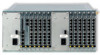
Modules MC+1-3 Technical Information ■ The MC+1-3 central control module is powered by the group 1 power supply unit. ■ The MC+1-3 central control module has a plug-in card (MSUB-MRAM) with 128 Mbytes of main (random access) memory. Please note: This plug-in card must not be exchanged by service personnel. In the event of a malfunction, the entire MC+1-3 central control module must be sent in for repair. ■ The MC+1-3 central control module has a CompactFlash slot (MSUB-MFL, PCMCIA interface) for CompactFlash cards. The following data are stored on the CompactFlash card: the OpenCom 510 firmware, the system terminal software, the configuration data and all customer data such as audio files for the internal voice mail system. Note: Only licensed cards may be used. These are currently (May 2004) special 256-Mbyte cards by SanDisk. Contact your DeTeWe distributor or local retailer if you want to purchase one of these cards. ■ The Ethernet port (10/100 Mbits/s) can be used to connect the OpenCom 510 to the LAN. ■ The V.24-1 interface can be used to connect additional apparatus, e.g. a computer for analysing call charges. For information on the V.24 interface pin assignment, refer to COM Port starting on page 52. Indicators There are four LEDs on the front of the MC+1-3 central control module. 73
-
 1
1 -
2
-
3
-
4
-
5
-
6
-
7
-
8
-
9
-
10
-
11
-
12
-
13
-
14
-
15
-
16
-
17
-
18
-
19
-
20
-
21
-
22
-
23
-
24
-
25
-
26
-
27
-
28
-
29
-
30
-
31
-
32
-
33
-
34
-
35
-
36
-
37
-
38
-
39
-
40
-
41
-
42
-
43
-
44
-
45
-
46
-
47
-
48
-
49
-
50
-
51
-
52
-
53
-
54
-
55
-
56
-
57
-
58
-
59
-
60
-
61
-
62
-
63
-
64
-
65
-
66
-
67
-
68
-
69
-
 70
70 -
 71
71 -
 72
72 -
 73
73 -
 74
74 -
 75
75 -
 76
76 -
 77
77 -
 78
78 -
 79
79 -
 80
80 -
81
-
82
-
83
-
84
-
85
-
86
-
87
-
88
-
89
-
90
-
91
-
92
-
93
-
94
-
95
-
96
-
97
-
98
-
99
-
100
-
101
-
102
-
103
-
104
-
105
-
106
-
107
-
108
-
109
-
110
-
111
-
112
-
113
-
114
-
115
-
116
-
117
-
118
-
119
-
120
-
121
-
122
-
123
-
124
-
125
-
126
-
127
-
128
-
129
-
130
-
131
-
132
-
133
-
134
-
135
-
136
-
137
-
138
-
139
-
140
-
141
-
142
-
143
-
144
-
145
-
146
-
147
-
148
-
149
-
150
-
151
-
152
-
153
-
154
-
155
-
156
-
157
-
158
-
159
-
160
-
161
-
162
-
163
-
164
-
165
-
166
-
167
-
168
-
169
-
170
-
171
-
172
-
173
-
174
-
175
-
176
-
177
-
178
-
179
-
180
-
181
-
182
-
183
-
184
-
185
-
186
-
187
-
188
-
189
-
190
-
191
-
192
-
193
-
194
-
195
-
196
-
197
-
198
-
199
-
200
-
201
-
202
-
203
-
204
-
205
-
206
-
207
-
208
-
209
-
210
-
211
-
212
-
213
-
214
-
215
-
216
-
217
-
218
-
219
-
220
-
221
-
222
-
223
-
224
 |
 |
