Aastra OpenCom 510 User Guide - Page 33
Installing Interface Cards, PBX Configuration: Ports: Slots, Configurator, CAUTION
 |
View all Aastra OpenCom 510 manuals
Add to My Manuals
Save this manual to your list of manuals |
Page 33 highlights
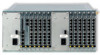
Installation Installing Modules 4.4.4 Installing Interface Cards Interface cards can be installed or exchanged with the system powered up ("hotplugging"). Proceed as follows: 1. If you want to exchange an interface card, the slot for this card needs to be deactivated first. Open the PBX Configuration: Ports: Slots page in the Configurator. In the table row listing the card to be exchanged, click on Stop. The system then deactivates the slot. Any connections (telephone calls, data transfers) established through this card will be terminated. 2. Remove the screws with which the interface card is secured in the 1-12 frame and pull the card out. 3. Unpack the interface card and check whether it is the desired type. The type designation is printed on the front of the card. MX+S01-8 S0 2 S0 1 Detail: Printing on the front of an "MX+S01-8" type interface card CAUTION! Static charge can damage electronic devices. Observe the regulations regarding electrostatically sensitive components. 4. Carefully push the interface card into the corresponding slot. The printing on the front of the module should be at the top (see illustration in previous instruction). 31
-
 1
1 -
2
-
3
-
4
-
5
-
6
-
7
-
8
-
9
-
10
-
11
-
12
-
13
-
14
-
15
-
16
-
17
-
18
-
19
-
20
-
21
-
22
-
23
-
24
-
25
-
26
-
27
-
 28
28 -
 29
29 -
 30
30 -
 31
31 -
 32
32 -
 33
33 -
 34
34 -
 35
35 -
 36
36 -
 37
37 -
 38
38 -
39
-
40
-
41
-
42
-
43
-
44
-
45
-
46
-
47
-
48
-
49
-
50
-
51
-
52
-
53
-
54
-
55
-
56
-
57
-
58
-
59
-
60
-
61
-
62
-
63
-
64
-
65
-
66
-
67
-
68
-
69
-
70
-
71
-
72
-
73
-
74
-
75
-
76
-
77
-
78
-
79
-
80
-
81
-
82
-
83
-
84
-
85
-
86
-
87
-
88
-
89
-
90
-
91
-
92
-
93
-
94
-
95
-
96
-
97
-
98
-
99
-
100
-
101
-
102
-
103
-
104
-
105
-
106
-
107
-
108
-
109
-
110
-
111
-
112
-
113
-
114
-
115
-
116
-
117
-
118
-
119
-
120
-
121
-
122
-
123
-
124
-
125
-
126
-
127
-
128
-
129
-
130
-
131
-
132
-
133
-
134
-
135
-
136
-
137
-
138
-
139
-
140
-
141
-
142
-
143
-
144
-
145
-
146
-
147
-
148
-
149
-
150
-
151
-
152
-
153
-
154
-
155
-
156
-
157
-
158
-
159
-
160
-
161
-
162
-
163
-
164
-
165
-
166
-
167
-
168
-
169
-
170
-
171
-
172
-
173
-
174
-
175
-
176
-
177
-
178
-
179
-
180
-
181
-
182
-
183
-
184
-
185
-
186
-
187
-
188
-
189
-
190
-
191
-
192
-
193
-
194
-
195
-
196
-
197
-
198
-
199
-
200
-
201
-
202
-
203
-
204
-
205
-
206
-
207
-
208
-
209
-
210
-
211
-
212
-
213
-
214
-
215
-
216
-
217
-
218
-
219
-
220
-
221
-
222
-
223
-
224
 |
 |
