Aastra OpenCom 510 User Guide - Page 73
Operational Information, Slots, Backplane
 |
View all Aastra OpenCom 510 manuals
Add to My Manuals
Save this manual to your list of manuals |
Page 73 highlights
Modules MPS+1-AC ■ Right: If the right LED is constantly lit up green, the output voltage is -42 V. The LEDs only indicate that the voltage is present. They do not say anything about the voltage quality. Operational Information The MPS+1-AC power supply unit will be ready for operation as soon as it has been plugged into the designated slot (see Slots starting on page 27). The mains voltage of 230 V is drawn through the standard IEC connector. The output voltages are fed to the BPV+1-12 backplane through the 96-pin spring contact strip (see Backplane starting on page 34). In the event of a power failure, the power supply unit will generate a power failure signal. 71
-
 1
1 -
2
-
3
-
4
-
5
-
6
-
7
-
8
-
9
-
10
-
11
-
12
-
13
-
14
-
15
-
16
-
17
-
18
-
19
-
20
-
21
-
22
-
23
-
24
-
25
-
26
-
27
-
28
-
29
-
30
-
31
-
32
-
33
-
34
-
35
-
36
-
37
-
38
-
39
-
40
-
41
-
42
-
43
-
44
-
45
-
46
-
47
-
48
-
49
-
50
-
51
-
52
-
53
-
54
-
55
-
56
-
57
-
58
-
59
-
60
-
61
-
62
-
63
-
64
-
65
-
66
-
67
-
 68
68 -
 69
69 -
 70
70 -
 71
71 -
 72
72 -
 73
73 -
 74
74 -
 75
75 -
 76
76 -
 77
77 -
 78
78 -
79
-
80
-
81
-
82
-
83
-
84
-
85
-
86
-
87
-
88
-
89
-
90
-
91
-
92
-
93
-
94
-
95
-
96
-
97
-
98
-
99
-
100
-
101
-
102
-
103
-
104
-
105
-
106
-
107
-
108
-
109
-
110
-
111
-
112
-
113
-
114
-
115
-
116
-
117
-
118
-
119
-
120
-
121
-
122
-
123
-
124
-
125
-
126
-
127
-
128
-
129
-
130
-
131
-
132
-
133
-
134
-
135
-
136
-
137
-
138
-
139
-
140
-
141
-
142
-
143
-
144
-
145
-
146
-
147
-
148
-
149
-
150
-
151
-
152
-
153
-
154
-
155
-
156
-
157
-
158
-
159
-
160
-
161
-
162
-
163
-
164
-
165
-
166
-
167
-
168
-
169
-
170
-
171
-
172
-
173
-
174
-
175
-
176
-
177
-
178
-
179
-
180
-
181
-
182
-
183
-
184
-
185
-
186
-
187
-
188
-
189
-
190
-
191
-
192
-
193
-
194
-
195
-
196
-
197
-
198
-
199
-
200
-
201
-
202
-
203
-
204
-
205
-
206
-
207
-
208
-
209
-
210
-
211
-
212
-
213
-
214
-
215
-
216
-
217
-
218
-
219
-
220
-
221
-
222
-
223
-
224
 |
 |

Modules
MPS+1-AC
71
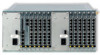
■
Right: If the right LED is constantly lit up green, the output voltage is –42 V.
The LEDs only indicate that the voltage is present. They do not say anything about
the voltage quality.
Operational Information
The MPS+1-AC power supply unit will be ready for operation as soon as it has been
plugged into the designated slot (see
Slots
starting on page 27).
The mains voltage of 230 V is drawn through the standard IEC connector. The
output voltages are fed to the BPV+1-12 backplane through the 96-pin spring
contact strip (see
Backplane
starting on page 34).
In the event of a power failure, the power supply unit will generate a power failure
signal.