Aastra OpenCom 510 User Guide - Page 37
Notes on Disconnecting the Mains Supply, Installing Modules, OpenCom 510: Backplane screws, DANGER
 |
View all Aastra OpenCom 510 manuals
Add to My Manuals
Save this manual to your list of manuals |
Page 37 highlights
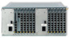
Installation Backplane ■ The MPS+1-AC power supply units and the MC+1-3 central control module are each connected by means of a 96-pin spring contact strip. ■ The interface modules are each connected by means of a 48-pin spring contact strip. The backplane also carries the system serial number (etched into the backplane chip). Should you need to exchange the backplane, proceed as follows: DANGER! Hazardous voltages inside the device! 1. Unplug all of the mains cables of the OpenCom 510 to disconnect the system from the mains supply. Refer to Notes on Disconnecting the Mains Supply starting on page 28. 2. Uninstall all modules and power supply units from the 1-12 frame (see Installing Modules starting on page 26). 3. Remove the screws on the backplane (see arrows in the illustration OpenCom 510: Backplane screws). Carefully remove the backplane from the 112 frame, pulling it out of the frame towards the front. OpenCom 510: Backplane screws 4. From the front, insert the new backplane into the 1-12 frame. Insert and tighten the screws to secure the backplane in the 1-12 frame. 35
-
 1
1 -
2
-
3
-
4
-
5
-
6
-
7
-
8
-
9
-
10
-
11
-
12
-
13
-
14
-
15
-
16
-
17
-
18
-
19
-
20
-
21
-
22
-
23
-
24
-
25
-
26
-
27
-
28
-
29
-
30
-
31
-
 32
32 -
 33
33 -
 34
34 -
 35
35 -
 36
36 -
 37
37 -
 38
38 -
 39
39 -
 40
40 -
 41
41 -
 42
42 -
43
-
44
-
45
-
46
-
47
-
48
-
49
-
50
-
51
-
52
-
53
-
54
-
55
-
56
-
57
-
58
-
59
-
60
-
61
-
62
-
63
-
64
-
65
-
66
-
67
-
68
-
69
-
70
-
71
-
72
-
73
-
74
-
75
-
76
-
77
-
78
-
79
-
80
-
81
-
82
-
83
-
84
-
85
-
86
-
87
-
88
-
89
-
90
-
91
-
92
-
93
-
94
-
95
-
96
-
97
-
98
-
99
-
100
-
101
-
102
-
103
-
104
-
105
-
106
-
107
-
108
-
109
-
110
-
111
-
112
-
113
-
114
-
115
-
116
-
117
-
118
-
119
-
120
-
121
-
122
-
123
-
124
-
125
-
126
-
127
-
128
-
129
-
130
-
131
-
132
-
133
-
134
-
135
-
136
-
137
-
138
-
139
-
140
-
141
-
142
-
143
-
144
-
145
-
146
-
147
-
148
-
149
-
150
-
151
-
152
-
153
-
154
-
155
-
156
-
157
-
158
-
159
-
160
-
161
-
162
-
163
-
164
-
165
-
166
-
167
-
168
-
169
-
170
-
171
-
172
-
173
-
174
-
175
-
176
-
177
-
178
-
179
-
180
-
181
-
182
-
183
-
184
-
185
-
186
-
187
-
188
-
189
-
190
-
191
-
192
-
193
-
194
-
195
-
196
-
197
-
198
-
199
-
200
-
201
-
202
-
203
-
204
-
205
-
206
-
207
-
208
-
209
-
210
-
211
-
212
-
213
-
214
-
215
-
216
-
217
-
218
-
219
-
220
-
221
-
222
-
223
-
224
 |
 |
