Aastra OpenCom 510 User Guide - Page 45
External ISDN Ports (S0 External), Installing Interface, Cards
 |
View all Aastra OpenCom 510 manuals
Add to My Manuals
Save this manual to your list of manuals |
Page 45 highlights
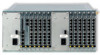
Interfaces and Connectible Terminals S0 Ports 1. Remove the interface card by following the instructions in Installing Interface Cards starting on page 31. 2. The DIP switches are protected by a plastic foil. Use a pointed tool such as a screwdriver to slide the DIP switches down (see arrow in the illustration MX+S01-8: Terminating resistors deactivated). ON 12 OpenCom 510 TR IAE TR IAE MX+S01-8: Terminating resistors deactivated Both ends of the S0 bus are terminated by terminating resistors; the terminating resistors must be deactivated (DIP switches set to "1 2"). 5.2.2 External ISDN Ports (S0 External) You can connect the OpenCom 510 to the NTBA or to a second OpenCom 510 for PBX cascading. To connect the OpenCom 510 to the NTBA, wire pins 3, 4, 5, 6 of the NTBA and of the OpenCom 510 1:1. To directly connect two OpenCom 510 systems via the external S0 ports, connect the RJ45 sockets of the systems by means of a crossed twisted-pair cable. The distance between the two PBXs must not exceed 1000 metres (see also PBX Networking starting on page 151). 43
-
 1
1 -
2
-
3
-
4
-
5
-
6
-
7
-
8
-
9
-
10
-
11
-
12
-
13
-
14
-
15
-
16
-
17
-
18
-
19
-
20
-
21
-
22
-
23
-
24
-
25
-
26
-
27
-
28
-
29
-
30
-
31
-
32
-
33
-
34
-
35
-
36
-
37
-
38
-
39
-
 40
40 -
 41
41 -
 42
42 -
 43
43 -
 44
44 -
 45
45 -
 46
46 -
 47
47 -
 48
48 -
 49
49 -
 50
50 -
51
-
52
-
53
-
54
-
55
-
56
-
57
-
58
-
59
-
60
-
61
-
62
-
63
-
64
-
65
-
66
-
67
-
68
-
69
-
70
-
71
-
72
-
73
-
74
-
75
-
76
-
77
-
78
-
79
-
80
-
81
-
82
-
83
-
84
-
85
-
86
-
87
-
88
-
89
-
90
-
91
-
92
-
93
-
94
-
95
-
96
-
97
-
98
-
99
-
100
-
101
-
102
-
103
-
104
-
105
-
106
-
107
-
108
-
109
-
110
-
111
-
112
-
113
-
114
-
115
-
116
-
117
-
118
-
119
-
120
-
121
-
122
-
123
-
124
-
125
-
126
-
127
-
128
-
129
-
130
-
131
-
132
-
133
-
134
-
135
-
136
-
137
-
138
-
139
-
140
-
141
-
142
-
143
-
144
-
145
-
146
-
147
-
148
-
149
-
150
-
151
-
152
-
153
-
154
-
155
-
156
-
157
-
158
-
159
-
160
-
161
-
162
-
163
-
164
-
165
-
166
-
167
-
168
-
169
-
170
-
171
-
172
-
173
-
174
-
175
-
176
-
177
-
178
-
179
-
180
-
181
-
182
-
183
-
184
-
185
-
186
-
187
-
188
-
189
-
190
-
191
-
192
-
193
-
194
-
195
-
196
-
197
-
198
-
199
-
200
-
201
-
202
-
203
-
204
-
205
-
206
-
207
-
208
-
209
-
210
-
211
-
212
-
213
-
214
-
215
-
216
-
217
-
218
-
219
-
220
-
221
-
222
-
223
-
224
 |
 |
