Asus P2-99B P2-99B User Manual - Page 18
System Memory DIMM
 |
View all Asus P2-99B manuals
Add to My Manuals
Save this manual to your list of manuals |
Page 18 highlights
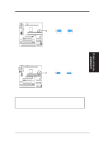
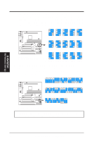
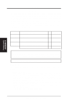
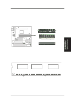
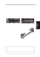
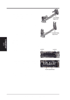
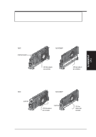
III. H/W SETUP System Memory III. HARDWARE SETUP 2. System Memory (DIMM) NOTE: No hardware or BIOS setup is required after adding or removing memory. This motherboard uses only Dual Inline Memory Modules (DIMMs). Sockets are available for 3.3Volt (power level) unbuffered Synchronous Dynamic Random Access Memory (SDRAM). The Intel 440ZX AGPset does not support ECC. However, ECC memory modules may still be used, but the ECC function will not be available. Memory speed setup is recommended through SDRAM Configuration under "Chipset Features Setup" in BIOS SETUP. Install memory in the following combinations: Location DIMM1 (Rows 0&1) DIMM2 (Rows 2&3) DIMM3 (Row 3) 168-pin DIMM SDRAM Single-sided Double-sided Single-sided Double-sided (Socket 3 must be empty) Single-sided (Socket 2 must be single-sided) (Double-sided cannot be used here!) Total System Memory (Max 512MB) Total Memory x1 x1 x1 = IMPORTANT! A total of four rows of memory is supported on this motherboard. One side (with memory chips) of the DIMM takes up one row. Because Socket 3 shares Row 3 with Socket 2, Socket 3 can only be used if Socket 2 does not use Row 3. WARNING! If Row 3 is used by both Socket 2 and 3, your system will not boot up! SPD Support This motherboard supports SPD DIMMs, and it is recommended that SPD DIMMs be used. General DIMM Notes • For the system CPU bus to operate above 100MHz, use only PC100-compli- ant DIMMs. When this motherboard operates at 100MHz, most system will not even boot if non-compliant modules are used because of the strict timing issues involved under this speed. If your DIMMs are not PC100-compliant, set the CPU external frequency to 66MHz for system stability. • ASUS motherboards support SPD (Serial Presence Detect) DIMMs. This is the memory of choice for best performance vs. stability. • SDRAM chips are generally thinner with higher pin density than EDO (Extended Data Output) chips. • BIOS shows SDRAM memory on bootup screen. 18 ASUS P2-99B User's Manual
-
 1
1 -
2
-
3
-
4
-
5
-
6
-
7
-
8
-
9
-
10
-
11
-
12
-
 13
13 -
 14
14 -
 15
15 -
 16
16 -
 17
17 -
 18
18 -
 19
19 -
 20
20 -
 21
21 -
 22
22 -
 23
23 -
24
-
25
-
26
-
27
-
28
-
29
-
30
-
31
-
32
-
33
-
34
-
35
-
36
-
37
-
38
-
39
-
40
-
41
-
42
-
43
-
44
-
45
-
46
-
47
-
48
-
49
-
50
-
51
-
52
-
53
-
54
-
55
-
56
-
57
-
58
-
59
-
60
-
61
-
62
-
63
-
64
-
65
-
66
-
67
-
68
-
69
-
70
-
71
-
72
-
73
-
74
-
75
-
76
-
77
-
78
-
79
-
80
-
81
-
82
-
83
-
84
-
85
-
86
-
87
-
88
-
89
-
90
-
91
-
92
-
93
-
94
-
95
-
96
 |
 |
