Asus P2-99B P2-99B User Manual - Page 82
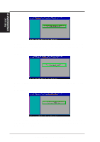
Setting up the ASUS CIDB
 |
View all Asus P2-99B manuals
Add to My Manuals
Save this manual to your list of manuals |
Page 82 highlights
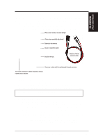
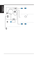
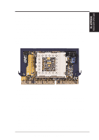
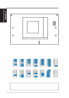
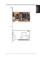
VII. APPENDIX ASUS CIDB Module VII. APPENDIX Setting up the ASUS CIDB JP1 OR CR2032 3V CLR Lithium Cell CON SW Buzzer MS2 MS1 +5 volt standby from power supply JP1 1 JP1 1 Enable Disable JP1: Enable/Disable the Photo Sensor 4 (sensitive) 5 32 CON best range 1 0 (not sensitive) CLR CLR CON: Sensitivity adjustment for the photo sensor, (0) is least sensitive and (5) is most sensitive Normal Clear Clear: Stops the sounding alarm SW 1 SW 1 Enable Disable MS2 MS1 MS1/MS2: Micro Switch from the chassis panel can be connected here to trigger the chassis intrusion alarm. SW: Enable/Disable chassis intrusion function in the motherboard ASUS CIDB Additional Considerations 1. All motherboards with CIDB: If there is no power to the motherboard (i.e. removing the power cord or turning the power supply's switch off) the alarm will not sound but the CIDB will still remember an intrusion event which BIOS and LDCM will detect on the next bootup. 2. Motherboard with chassis intrusion components: Photo sensor, switch, and memory will not operate with power removed. Power is required to send a signal to the motherboard's intrusion memory and buzzer. When using the CIDB on these motherboards, all the CIDB functions will be disabled, the motherboard's intrusion components must still be used. The CIDB can benefit these motherboards by providing a chassis switch which will operate even when the power is removed. Pins [2-3] of the SW jumper can be used for a momentary toggle switch and the CIDB's battery will be used to send an intrusion signal to the motherboard's intrusion memory. 82 ASUS P2-99B User's Manual
-
 1
1 -
2
-
3
-
4
-
5
-
6
-
7
-
8
-
9
-
10
-
11
-
12
-
13
-
14
-
15
-
16
-
17
-
18
-
19
-
20
-
21
-
22
-
23
-
24
-
25
-
26
-
27
-
28
-
29
-
30
-
31
-
32
-
33
-
34
-
35
-
36
-
37
-
38
-
39
-
40
-
41
-
42
-
43
-
44
-
45
-
46
-
47
-
48
-
49
-
50
-
51
-
52
-
53
-
54
-
55
-
56
-
57
-
58
-
59
-
60
-
61
-
62
-
63
-
64
-
65
-
66
-
67
-
68
-
69
-
70
-
71
-
72
-
73
-
74
-
75
-
76
-
 77
77 -
 78
78 -
 79
79 -
 80
80 -
 81
81 -
 82
82 -
 83
83 -
 84
84 -
 85
85 -
 86
86 -
 87
87 -
88
-
89
-
90
-
91
-
92
-
93
-
94
-
95
-
96
 |
 |
