Brother International HL 5030 Service Manual - Page 107
CAUTION, Remove the herical extension spring., Remove the lock lever.
 |
View all Brother International HL 5030 manuals
Add to My Manuals
Save this manual to your list of manuals |
Page 107 highlights
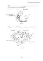
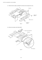
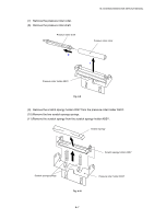
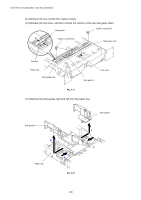
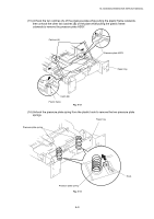
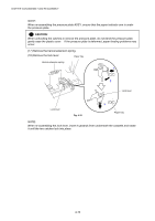
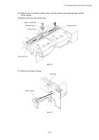
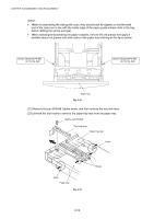
CHAPTER 4 DISASSEMBLY AND RE-ASSEMBLY NOTE: When re-assembling the pressure plate ASSY, ensure that the paper indicator arm is under the pressure plate. ! CAUTION: When unhooking the catches to remove the pressure plate, do not bend the pressure plate, gently ease the plastic cover. If the pressure plate is deformed, paper feeding problems may occur. (17) Remove the herical extension spring. (18) Remove the lock lever. Paper tray Herical extension spring 1 2 Lock lever Lock lever Fig. 4-15 3 Paper tray NOTE: When re-assembling the lock lever, insert it upwards from underneath the cassette and rotate it until the two catches lock into place. 4-10
-
 1
1 -
2
-
3
-
4
-
5
-
6
-
7
-
8
-
9
-
10
-
11
-
12
-
13
-
14
-
15
-
16
-
17
-
18
-
19
-
20
-
21
-
22
-
23
-
24
-
25
-
26
-
27
-
28
-
29
-
30
-
31
-
32
-
33
-
34
-
35
-
36
-
37
-
38
-
39
-
40
-
41
-
42
-
43
-
44
-
45
-
46
-
47
-
48
-
49
-
50
-
51
-
52
-
53
-
54
-
55
-
56
-
57
-
58
-
59
-
60
-
61
-
62
-
63
-
64
-
65
-
66
-
67
-
68
-
69
-
70
-
71
-
72
-
73
-
74
-
75
-
76
-
77
-
78
-
79
-
80
-
81
-
82
-
83
-
84
-
85
-
86
-
87
-
88
-
89
-
90
-
91
-
92
-
93
-
94
-
95
-
96
-
97
-
98
-
99
-
100
-
101
-
 102
102 -
 103
103 -
 104
104 -
 105
105 -
 106
106 -
 107
107 -
 108
108 -
 109
109 -
 110
110 -
 111
111 -
 112
112 -
113
-
114
-
115
-
116
-
117
-
118
-
119
-
120
-
121
-
122
-
123
-
124
-
125
-
126
-
127
-
128
-
129
-
130
-
131
-
132
-
133
-
134
-
135
-
136
-
137
-
138
-
139
-
140
-
141
-
142
-
143
-
144
-
145
-
146
-
147
-
148
-
149
-
150
-
151
-
152
-
153
-
154
-
155
-
156
-
157
-
158
-
159
-
160
-
161
-
162
-
163
-
164
-
165
-
166
-
167
-
168
-
169
-
170
-
171
-
172
-
173
-
174
-
175
-
176
-
177
-
178
-
179
-
180
-
181
-
182
-
183
-
184
-
185
-
186
-
187
-
188
-
189
-
190
-
191
-
192
-
193
-
194
-
195
-
196
-
197
-
198
-
199
-
200
-
201
-
202
-
203
-
204
-
205
-
206
-
207
-
208
-
209
-
210
-
211
-
212
-
213
-
214
-
215
-
216
-
217
-
218
-
219
-
220
-
221
-
222
-
223
-
224
-
225
-
226
-
227
-
228
-
229
-
230
-
231
-
232
-
233
-
234
-
235
-
236
-
237
-
238
-
239
-
240
-
241
-
242
-
243
-
244
-
245
-
246
-
247
-
248
-
249
-
250
-
251
-
252
-
253
-
254
-
255
-
256
-
257
-
258
-
259
-
260
-
261
-
262
-
263
-
264
-
265
 |
 |

CHAPTER 4 DISASSEMBLY AND RE-ASSEMBLY
4-10
NOTE:
When re-assembling the pressure plate ASSY, ensure that the paper indicator arm is under
the pressure plate.
!
CAUTION:
When unhooking the catches to remove the pressure plate, do not bend the pressure plate,
gently ease the plastic cover.
If the pressure plate is deformed, paper feeding problems may
occur.
(17) Remove the herical extension spring.
(18) Remove the lock lever.
Fig. 4-15
NOTE:
When re-assembling the lock lever, insert it upwards from underneath the cassette and rotate
it until the two catches lock into place.
Herical extension spring
Lock lever
1
2
3
Paper tray
Paper tray
Lock lever