Brother International HL 5030 Service Manual - Page 95
Exposure stage, exposed area is reduced, forming the electrostatic image to be printed.
 |
View all Brother International HL 5030 manuals
Add to My Manuals
Save this manual to your list of manuals |
Page 95 highlights
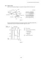
HL-5030/5040/5050/5070N SERVICE MANUAL 2.6.2 Exposure stage After the drum is positively charged, it is exposed to the light emitted from the laser unit. Laser detector Laser diode Drum Paper Laser beam f θ lens Polygon mirror Lens Motor Fig. 3-41 Laser beam The area exposed to the laser beam is the image to be printed. The surface potential of the exposed area is reduced, forming the electrostatic image to be printed. Surface potential (V) +870 +400 +150 Drum sleeve 0 1 Cycle of drum 1 2 3 (a) (b) Time Fig. 3-42 1 Primary charging 2 Laser beam exposure and developing (a) Unexposed area (Non image area) (b) Exposed area (Image area) 3 Transfer the image to paper 3-27
-
 1
1 -
2
-
3
-
4
-
5
-
6
-
7
-
8
-
9
-
10
-
11
-
12
-
13
-
14
-
15
-
16
-
17
-
18
-
19
-
20
-
21
-
22
-
23
-
24
-
25
-
26
-
27
-
28
-
29
-
30
-
31
-
32
-
33
-
34
-
35
-
36
-
37
-
38
-
39
-
40
-
41
-
42
-
43
-
44
-
45
-
46
-
47
-
48
-
49
-
50
-
51
-
52
-
53
-
54
-
55
-
56
-
57
-
58
-
59
-
60
-
61
-
62
-
63
-
64
-
65
-
66
-
67
-
68
-
69
-
70
-
71
-
72
-
73
-
74
-
75
-
76
-
77
-
78
-
79
-
80
-
81
-
82
-
83
-
84
-
85
-
86
-
87
-
88
-
89
-
 90
90 -
 91
91 -
 92
92 -
 93
93 -
 94
94 -
 95
95 -
 96
96 -
 97
97 -
 98
98 -
 99
99 -
 100
100 -
101
-
102
-
103
-
104
-
105
-
106
-
107
-
108
-
109
-
110
-
111
-
112
-
113
-
114
-
115
-
116
-
117
-
118
-
119
-
120
-
121
-
122
-
123
-
124
-
125
-
126
-
127
-
128
-
129
-
130
-
131
-
132
-
133
-
134
-
135
-
136
-
137
-
138
-
139
-
140
-
141
-
142
-
143
-
144
-
145
-
146
-
147
-
148
-
149
-
150
-
151
-
152
-
153
-
154
-
155
-
156
-
157
-
158
-
159
-
160
-
161
-
162
-
163
-
164
-
165
-
166
-
167
-
168
-
169
-
170
-
171
-
172
-
173
-
174
-
175
-
176
-
177
-
178
-
179
-
180
-
181
-
182
-
183
-
184
-
185
-
186
-
187
-
188
-
189
-
190
-
191
-
192
-
193
-
194
-
195
-
196
-
197
-
198
-
199
-
200
-
201
-
202
-
203
-
204
-
205
-
206
-
207
-
208
-
209
-
210
-
211
-
212
-
213
-
214
-
215
-
216
-
217
-
218
-
219
-
220
-
221
-
222
-
223
-
224
-
225
-
226
-
227
-
228
-
229
-
230
-
231
-
232
-
233
-
234
-
235
-
236
-
237
-
238
-
239
-
240
-
241
-
242
-
243
-
244
-
245
-
246
-
247
-
248
-
249
-
250
-
251
-
252
-
253
-
254
-
255
-
256
-
257
-
258
-
259
-
260
-
261
-
262
-
263
-
264
-
265
 |
 |

HL-5030/5040/5050/5070N SERVICE MANUAL
3-27
2.6.2
Exposure stage
After the drum is positively charged, it is exposed to the light emitted from the laser unit.
Fig. 3-41
The area exposed to the laser beam is the image to be printed.
The surface potential of the
exposed area is reduced, forming the electrostatic image to be printed.
Fig. 3-42
Drum
Lens
Laser beam
Polygon mirror
Paper
Laser detector
Laser diode
Motor
Laser beam
f
θ
lens
3
Primary charging
Laser beam exposure and developing
(a) Unexposed area
(Non image area)
(b) Exposed area
(Image area)
Transfer the image to paper
Time
Drum
sleeve
0
2
1
1
2
3
(a)
(b)
+150
+400
+870
Surface
potential (V)
1 Cycle of drum