Cisco 3524XL Hardware Installation Guide
Cisco 3524XL - Catalyst Enterprise Edition Switch Manual
 |
UPC - 746320224220
View all Cisco 3524XL manuals
Add to My Manuals
Save this manual to your list of manuals |
Cisco 3524XL manual content summary:
- Cisco 3524XL | Hardware Installation Guide - Page 1
Catalyst 3500 Series XL Hardware Installation Guide May 2000 Corporate Headquarters Cisco Systems, Inc. 170 West Tasman Drive San Jose, CA 95134-1706 USA http://www.cisco.com Tel: 408 526-4000 800 553-NETS (6387) Fax: 408 526-4100 Customer Order Number: DOC-786456= Text Part Number: 78-6456-03 - Cisco 3524XL | Hardware Installation Guide - Page 2
the instruction manual, may Access Registrar, AccessPath, Any to Any, AtmDirector, Browse with Me, CCDA, CCDE, CCDP, CCIE, CCNA, CCNP, CCSI, CD-PAC, the Cisco logo, Cisco Certified Internetwork Expert logo, CiscoLink, the Cisco Management Connection logo, the Cisco NetWorks logo, the Cisco Powered - Cisco 3524XL | Hardware Installation Guide - Page 3
IOS, the Cisco IOS logo, Cisco Systems, the Cisco Systems logo, the Cisco Systems Cisco Press logo, Enterprise/Solver, EtherChannel, EtherSwitch, FastHub, FastLink, FastPAD, FastSwitch, GeoTel, IOS, IP/TV, IPX, LightStream, LightSwitch, MICA, NetRanger, Post-Routing, Pre-Routing, Registrar, - Cisco 3524XL | Hardware Installation Guide - Page 4
- Cisco 3524XL | Hardware Installation Guide - Page 5
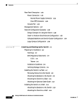
Assistance xv Cisco Connection Online xv Technical Assistance Center xvi Documentation Feedback xvii Product Overview 1-1 Features 1-1 Front-Panel Description 1-6 10/100 Ports 1-8 GBIC Module Slots 1-10 LEDs 1-12 System LED 1-15 RPS LED 1-16 Port LEDs and Modes 1-18 Catalyst 3500 Series XL Hardware - Cisco 3524XL | Hardware Installation Guide - Page 6
1-25 Internal Power Supply Connector 1-25 Cisco RPS Connector 1-25 Console Port 1-26 Management Options 1-27 Network Configuration Examples 1-28 Design Concepts for Using the Switch 1-28 Small- to Medium-Sized Network Configuration 1-32 Collapsed Backbone and Switch Cluster Configuration 1-34 Large - Cisco 3524XL | Hardware Installation Guide - Page 7
or Terminal to the Console Port 2-22 Assigning Switch Information 2-24 Using the Setup Program 2-24 Using BOOTP 2-28 Default Configuration Settings 2-29 Where to Go Next 2-30 Troubleshooting 3-1 Understanding POST Results 3-2 Diagnosing Problems 3-3 Technical Specifications A-1 Connector and Cable - Cisco 3524XL | Hardware Installation Guide - Page 8
17 Grounded Equipment Warning C-19 Supply Circuit Warning C-20 No On/Off Switch Warning C-21 Power Supply Warning C-22 Lightning Activity Warning C-25 Product Disposal Warning C-26 Chassis Warning-Rack-Mounting and Servicing C-27 Catalyst 3500 Series XL Hardware Installation Guide viii 78-6456-03 - Cisco 3524XL | Hardware Installation Guide - Page 9
features of Catalyst 3500 series XL switches. It describes the physical and performance characteristics of the switches in the series, explains how to install a switch and set up its initial configuration, provides troubleshooting information, and describes how to assign IP information to the switch - Cisco 3524XL | Hardware Installation Guide - Page 10
set up the switch initial configuration. Chapter 3, "Troubleshooting," describes how to identify and resolve some of the problems that might arise when you are installing the switch. Appendix A, "Technical Specifications," lists the physical and environmental specifications for the switches and the - Cisco 3524XL | Hardware Installation Guide - Page 11
suggestions or references to materials not contained in this manual. Caution Means reader be careful. In this situation, te zijn van de bij elektrische schakelingen betrokken risico's en dient u op de hoogte te zijn van standaard maatregelen 03 Catalyst 3500 Series XL Hardware Installation Guide xi - Cisco 3524XL | Hardware Installation Guide - Page 12
che accompagna questo dispositivo. Advarsel Dette varselsymbolet betyr fare. Du befinner deg i en situasjon som kan føre til personskade. Før du utfører arbeid på og sikkerhetsinformasjon) som ble levert med denne enheten. Catalyst 3500 Series XL Hardware Installation Guide xii 78-6456-03 - Cisco 3524XL | Hardware Installation Guide - Page 13
con este dispositivo. Varning! Denna varningssymbol signalerar fara. Du befinner dig i en situation som kan leda till personskada. Innan du utför arbete på någon och säkerhetsinformation), vilket medföljer denna anordning. 78-6456-03 Catalyst 3500 Series XL Hardware Installation Guide xiii - Cisco 3524XL | Hardware Installation Guide - Page 14
products, refer to the following publications: • Quick Start: Catalyst 3500 Series XL Cabling and Setup • Cisco IOS Desktop Switching Software Configuration Guide • Cisco IOS Desktop Switching Command Reference (online only) • Cisco Cluster Management Suite online help provides detailed procedures - Cisco 3524XL | Hardware Installation Guide - Page 15
and partners can self-register on CCO to obtain additional personalized information and services. Registered users may order products, check on the status of an order and view benefits specific to their relationships with Cisco. 78-6456-03 Catalyst 3500 Series XL Hardware Installation Guide xv - Cisco 3524XL | Hardware Installation Guide - Page 16
com In North America, TAC can be reached at 800 553-2447 or 408 526-7209. For other telephone numbers and TAC e-mail addresses worldwide, consult the following web site: http://www.cisco.com/warp/public/687/Directory/DirTAC.shtml. Catalyst 3500 Series XL Hardware Installation Guide xvi 78-6456-03 - Cisco 3524XL | Hardware Installation Guide - Page 17
Technical Assistance Documentation Feedback If you are reading Cisco product documentation on the World Wide Web, you card behind the front cover. Otherwise, you can mail your comments to the following address: Cisco Systems, Inc. Document Resource Connection 170 West Tasman Drive San Jose, CA 95134 - Cisco 3524XL | Hardware Installation Guide - Page 18
Obtaining Technical Assistance Preface xviii Catalyst 3500 Series XL Hardware Installation Guide 78-6456-03 - Cisco 3524XL | Hardware Installation Guide - Page 19
from other network devices. A feature specific to the Catalyst 3524-PWR XL switch is its ability to provide inline power to Cisco IP Phones. (Phone adapters are not required when connecting to the Catalyst 3524-PWR XL 10/100 switch ports.) Figure 1-1 shows the switch models in the series, and - Cisco 3524XL | Hardware Installation Guide - Page 20
ports 2 GBIC-based gigabit module slots WS-C3524-XL 24 autosensing 10/100 Ethernet ports 2 fixed GBIC-based gigabit module slots WS-C3524-PWR-XL 24 autosensing 10/100 inline-power Ethernet ports 2 GBIC-based gigabit module slots WS-C3548-XL 48 autosensing 10/100 Ethernet ports 2 GBIC - Cisco 3524XL | Hardware Installation Guide - Page 21
GBICs with the Catalyst 3508G XL switch) Management • Cisco IOS command-line interface (CLI) through the console port or Telnet • CiscoView device-management application • Cluster Management Suite, a web-based tool for managing switch clusters or an individual switch through a single IP address - Cisco 3524XL | Hardware Installation Guide - Page 22
1-2 Catalyst 3512, 3524, 3524-PWR, and 3548 XL Features Feature Performance and Configuration Description • Autonegotiation of speed and duplex operation on 10/100 Ethernet ports • 12, 24, or 48 10/100 Ethernet ports and 2 GBIC-based Gigabit Ethernet slots • Support for up to 250 port-based VLANs - Cisco 3524XL | Hardware Installation Guide - Page 23
Overview Features Table 1-2 Catalyst 3512, 3524, 3524-PWR, and 3548 XL Features (continued) Feature Description (continued) Management • Cisco IOS CLI through the console port or Telnet • CiscoView device-management application • Cluster Management Suite, a web-based tool for managing switch - Cisco 3524XL | Hardware Installation Guide - Page 24
/100 ports. The front panel of the Catalyst 3512, 3524, 3524-PWR and 3548 XL switches (Figure 1-3, Figure 1-4, Figure 1-5, and Figure 1-6) have 10/100 RJ-45 ports and two 1000BaseX GBIC module slots. All Catalyst 3500 XL switches have a set of LEDs and a Mode button. (The Catalyst 3548 XL switch has - Cisco 3524XL | Hardware Installation Guide - Page 25
11X 12X 13 14 13X 15 16 17 18 19 20 21 22 23 24 23X 14X 24X 10/100 ports Figure 1-5 Catalyst 3524-PWR XL Switch 1 2 GBIC module slots 30291 12 1X 34 56 78 MODE SYSTEM RPS STATUS 2X DUPLX SPEED LINE PWR 9 10 11 12 11X 12X 13 14 13X 15 16 17 18 19 20 - Cisco 3524XL | Hardware Installation Guide - Page 26
also supports autonegotiation, the switch port negotiates the best connection (that is, the fastest line speed that both devices support and full-duplex transmission, if the attached device supports it) and configures itself accordingly. Catalyst 3500 Series XL Hardware Installation Guide 1-8 78 - Cisco 3524XL | Hardware Installation Guide - Page 27
Catalyst 3512, 3524, 3524-PWR, and 3548 XL switches provide protocol support for Cisco IP Phones. The Catalyst 3548 and 3524-PWR XL switches also support per-port priority override. Refer to the Cisco IOS Desktop Switching Software Configuration Guide for more information about these features. Cisco - Cisco 3524XL | Hardware Installation Guide - Page 28
GBIC module for creating a 1-Gbps stack configuration of up to nine Catalyst 3500 XL switches. The GigaStack GBIC supports one full-duplex link (in a point-to-point configuration) or up to nine half-duplex links (in a stack configuration) to other Gigabit Ethernet devices. Using the required Cisco - Cisco 3524XL | Hardware Installation Guide - Page 29
SPEED 2 3 1000BaseX GBIC module GBIC module slot Figure 1-8 Installing a GigaStack GBIC Module in the Switch Metal flap door 22081 1 SYSTEM RPS MODE STATUS UTIL DUPLX SPEED 2 3 1 2 GigaStack GBIC GBIC module slot 78-6456-03 Catalyst 3500 Series XL Hardware Installation Guide 1-11 - Cisco 3524XL | Hardware Installation Guide - Page 30
Manager page. The Cisco IOS Desktop Switching Software Configuration Guide describes how to use the Cluster Management Suite to monitor individual switches and how to use cluster management software to monitor all the switches in a cluster. Figure 1-9 Catalyst 3508G XL LEDs GBIC module slot LEDs - Cisco 3524XL | Hardware Installation Guide - Page 31
Chapter 1 Product Overview Figure 1-10 Catalyst 3512 and 3524 XL LEDs Port LEDs Front-Panel Description 22028 MODE SYSTEM RPS STATUS UTIL DUPLX SPEED Mode button 12 1X 34 56 78 9 10 11 12 11X 2X 12X System LED Redundant power system LED Status LED Utilization LED Duplex LED Speed LED 78 - Cisco 3524XL | Hardware Installation Guide - Page 32
Figure 1-11 Catalyst 3524-PWR XL LEDs Port LEDs Chapter 1 Product Overview 30292 MODE SYSTEM RPS STATUS DUPLX SPEED LINE PWR Mode button 12 1X 34 56 78 9 10 11 12 11X 2X 12X System LED Redundant power system LED Status LED Duplex LED Speed LED Line power LED 1-14 Catalyst 3500 Series - Cisco 3524XL | Hardware Installation Guide - Page 33
powered on. System is operating normally. System is receiving power but is not functioning properly. For information on the System LED colors during POST, see the "Powering On the Switch and Running POST" section on page 2-15. 78-6456-03 Catalyst 3500 Series XL Hardware Installation Guide 1-15 - Cisco 3524XL | Hardware Installation Guide - Page 34
and Table 1-5 list the LED colors and their meanings. Note The Cisco RPS 600 (model PWR600-AC-RPS) supports the Catalyst 3512, 3524, 3548, and 3508 XL switches. Table 1-4 RPS LED for the Catalyst 3508, 3512, 3524, and 3548 XL Switches Color Off Solid green Blinking green RPS Status RPS is off or - Cisco 3524XL | Hardware Installation Guide - Page 35
Chapter 1 Product Overview Front-Panel Description Note The Cisco RPS 300 (model PWR300-AC-RPS) supports the Catalyst 3524-PWR XL switch. Table 1-5 RPS LED for the Catalyst 3524-PWR XL Switch Color Off Solid green Blinking green Solid amber Blinking amber RPS Status RPS is off or is not - Cisco 3524XL | Hardware Installation Guide - Page 36
mode. Note To change the port mode in the Catalyst 3548 XL switch, press the Mode label. Table 1-6 Port Mode LEDs Mode LED STAT UTL DUPLX SPEED LINE PWR Port Mode Port status Switch utilization Port duplex mode Port speed Port inline power Description The port status. This is the default mode - Cisco 3524XL | Hardware Installation Guide - Page 37
in Different Modes on the Catalyst 3508, 3512, 3524, and 3548 XL Switches Port Mode STATUS (port status) LED Color Off Solid Port is not forwarding. Port was disabled by management or an address violation or was blocked by Spanning Tree Protocol (STP). Note After a port is reconfigured, the port - Cisco 3524XL | Hardware Installation Guide - Page 38
power is off. Inline power is on. If the Cisco IP Phone is receiving power from an AC power source, the port LED is off even if the IP phone is connected to the switch port. The LED turns green only when the switch port is providing power. 1-20 Catalyst 3500 Series XL Hardware Installation Guide - Cisco 3524XL | Hardware Installation Guide - Page 39
1-16 show the bandwidth utilization percentages displayed by the right-most LEDs. 22006 Note The port LEDs on the Catalyst 3524-PWR XL switch do not show bandwidth utilization. To find out the switch bandwidth usage, use the Device Bandwidth Graph on VSM. Figure 1-13 Bandwidth Utilization for the - Cisco 3524XL | Hardware Installation Guide - Page 40
32X 34X 48X < 25% + 25% - 49% + 50% + XL 1 2 If all port LEDs on the Catalyst 3548 XL switch are green, the switch is using 50 percent or more of its total bandwidth capacity. If all 10/100 port LEDs are green and the lower GBIC LED is amber, the switch is using between 25 and 50 percent of its - Cisco 3524XL | Hardware Installation Guide - Page 41
+12V***@3A AC power connector RJ-45 console port Redundant power system connector Figure 1-18 Catalyst 3512 and 3524 XL Rear Panel Fans 18964 RATING 100-127/200-240V~ 1.0A/0.5A 50-60HZ AC power connector 78-6456-03 CONSOLE DC INPUTS FOR REMOTE POWER SUPPLY SPECIFIED IN MANUAL. +5V @24A, +12V - Cisco 3524XL | Hardware Installation Guide - Page 42
Figure 1-19 Catalyst 3524-PWR XL Rear Panel RATING 100-127/200-240V~ 3.5A/1.8A 50-60HZ DC INPUTS FOR REMOTE POWER SUPPLY SPECIFIED IN MANUAL. -48V @3A, +12V @6A CONSOLE AC power connector Redundant power system connector RJ-45 console port Figure 1-20 Catalyst 3548 XL Rear Panel Chapter - Cisco 3524XL | Hardware Installation Guide - Page 43
support specific Catalyst 3500 XL switches: • Cisco RPS 600 (model PWR600-AC-RPS)-Supports the Catalyst 3512, 3524, 3548, and 3508 XL switches • Cisco RPS 300 (model PWR300-AC-RPS)-Supports the Catalyst 3524-PWR XL switch RPS Connector on the Catalyst 3508, 3512, 3524, and 3548 XL Switches The Cisco - Cisco 3524XL | Hardware Installation Guide - Page 44
the switch console port to a terminal. You can order a kit (part number ACS-DSBUASYN=) containing that adapter from Cisco. For console port and adapter pinout information, see the "Cable and Adapter Specifications" section on page B-4. 1-26 Catalyst 3500 Series XL Hardware Installation Guide 78 - Cisco 3524XL | Hardware Installation Guide - Page 45
refer to the Cisco IOS Desktop Switching Software Configuration Guide and the online help for these applications. • Cisco IOS command-line interface (CLI) Connect a PC or terminal directly to the console port, located on the rear panel of the switch, to access the CLI. If the switch is connected to - Cisco 3524XL | Hardware Installation Guide - Page 46
relative priority of the network applications they use. Table 1-9 describes what can cause network performance to degrade and describes how you can configure your network to increase the bandwidth available to your network users. 1-28 Catalyst 3500 Series XL Hardware Installation Guide 78-6456-03 - Cisco 3524XL | Hardware Installation Guide - Page 47
or Gigabit Ethernet switch ports so that they have their own Fast Ethernet or Gigabit Ethernet segment. • Use the Fast EtherChannel or Gigabit EtherChannel feature between the switch and its connected servers and routers. • An evolving demand for IP telephony • Use quality of service (QoS) to - Cisco 3524XL | Hardware Installation Guide - Page 48
the Catalyst 3508G XL switch as a switch cluster to manage them through a single IP address. • High-performance workgroup-For users who require high-speed access to network resources, use gigabit GBIC modules to connect the switches directly to a backbone switch in a star configuration. Each switch - Cisco 3524XL | Hardware Installation Guide - Page 49
Configurations with Catalyst 3500 XL Switches Cost-Effective Wiring Closet Catalyst 3548 XL switch Catalyst 3548 XL GigaStack cluster High-Performance Workgroup Catalyst 3508 XL or 4908G-L3 switch Catalyst 3500 XL cluster Redundant Gigabit Backbone Catalyst 4908G-L3 switch Catalyst 4908G - Cisco 3524XL | Hardware Installation Guide - Page 50
performance from a server, connect the server to a Fast Ethernet or Fast EtherChannel switch port. Connecting a router to a Fast Ethernet switch port provides multiple, simultaneous access to the Internet through one line. 1-32 Catalyst 3500 Series XL Hardware Installation Guide 78-6456-03 - Cisco 3524XL | Hardware Installation Guide - Page 51
Network Configuration Cisco 2600 router Catalyst 3500 XL GigaStack cluster 100 Mbps (200 Mbps full duplex) Gigabit server 1 Gbps (2 Gbps full duplex) Gigabit server 10/100 Mbps (20/200 Mbps full duplex) Single workstations 33091 78-6456-03 Catalyst 3500 Series XL Hardware Installation Guide - Cisco 3524XL | Hardware Installation Guide - Page 52
the Catalyst 3524-PWR XL switches and to the 10/100 ports on the Catalyst 3500 and 2900 XL switches. These multiservice switch ports automatically detect if an IP phone is connected. You also configure each port for 802.1p/Q QoS to give forwarding priority to voice traffic over data traffic. Cisco - Cisco 3524XL | Hardware Installation Guide - Page 53
Fast EtherChannel (400 Mbps full duplex Fast EtherChannel) Catalyst 3524-PWR XL GigaStack cluster IP IP AC power source Workstations running Cisco SoftPhone software IP IP Cisco IP Phones IP IP IP Cisco IP Phones 33092 78-6456-03 Catalyst 3500 Series XL Hardware Installation Guide 1-35 - Cisco 3524XL | Hardware Installation Guide - Page 54
earlier workgroup configurations to create workgroups with gigabit uplinks to the Catalyst 6500 switch. For example, you can use switch clusters that have a mix of Catalyst 3500 and 2900 XL switches. The Catalyst 6500 switch provides the workgroups with gigabit access to core resources: • Cisco 7000 - Cisco 3524XL | Hardware Installation Guide - Page 55
Figure 1-24 Large Campus Configuration WAN IP telephony network or PSTN Cisco CallManager Cisco 7200 Cisco access or 7500 router gateway Servers Catalyst 6500 switch Catalyst 3500 XL and 2900 XL GigaStack cluster 1 Gbps (2 Gbps full duplex) Catalyst 3524-PWR XL GigaStack cluster IP IP AC - Cisco 3524XL | Hardware Installation Guide - Page 56
Network Configuration Examples Chapter 1 Product Overview 1-38 Catalyst 3500 Series XL Hardware Installation Guide 78-6456-03 - Cisco 3524XL | Hardware Installation Guide - Page 57
and start up your Catalyst 3500 XL switches and to interpret the power-on self-test (POST Power-on procedures • Connection procedures • Set up procedures for initial configuration • Default configuration settings • Where to go next 78-6456-03 Catalyst 3500 Series XL Hardware Installation Guide - Cisco 3524XL | Hardware Installation Guide - Page 58
chassis on any other equipment. If the chassis falls, it can cause severe bodily injury and equipment damage. Warning The plug-socket combination must be accessible at all times because it serves as the main disconnecting device. Catalyst 3500 Series XL Hardware Installation Guide 2-2 78-6456-03 - Cisco 3524XL | Hardware Installation Guide - Page 59
voltages are present within the power supply even when the power switch is off and the power cord is connected. For systems without a power switch, line voltages are present within the power supply when the power cord is connected. 78-6456-03 Catalyst 3500 Series XL Hardware Installation Guide 2-3 - Cisco 3524XL | Hardware Installation Guide - Page 60
the Catalyst 3524-PWR XL switch: Warning Attach only the Cisco RPS (model PWR300-AC-RPS) to the RPS receptacle. EMC Regulatory Statements U.S.A. Taiwan U.S. regulatory information for this product is in the front matter of this manual. 15456 Catalyst 3500 Series XL Hardware Installation Guide - Cisco 3524XL | Hardware Installation Guide - Page 61
A, "Technical Specifications." • Clearance to front and rear panels is such that - Front-panel indicators can be easily read. - Access to ports is sufficient for unrestricted cabling. - Rear-panel power connector is within reach of an AC power receptacle. • Airflow around the switch and through the - Cisco 3524XL | Hardware Installation Guide - Page 62
support. Return all packing materials to the shipping container, and save it. The switch is shipped with the following items: • Quick Start: Catalyst 3500 Series XL Cabling and Setup • This Catalyst 3500 Series XL Hardware Installation Guide • Cisco IOS Desktop Switching Software Configuration Guide - Cisco 3524XL | Hardware Installation Guide - Page 63
switches in the series (Catalyst 3512, 3524, 3524-PWR, and 3548 XL) can also be installed as shown here. Figure 2-1 Bracket Mounting Points 19" rack mount point 24" rack mount point 38398 78-6456-03 19" rack mount point 24" rack mount point Catalyst 3500 Series XL Hardware Installation Guide - Cisco 3524XL | Hardware Installation Guide - Page 64
or a 24-inch standard rack, follow the instructions described in these procedures: • Removing screws from the switch • Attaching the brackets to the switch • Mounting the switch in a rack • Attaching the optional cable guide Removing Screws from the Switch If you plan to install the Catalyst 3548 XL - Cisco 3524XL | Hardware Installation Guide - Page 65
to attach the long side of the bracket to the switch. • For a 24-inch rack, use the supplied number-8 Phillips truss-head screws to attach the Configuration 2 3 1 SYSTEM RPS MODE STATUS UTIL DUPLX SPEED 2 3 24" Configuration 22438 78-6456-03 Catalyst 3500 Series XL Hardware Installation Guide - Cisco 3524XL | Hardware Installation Guide - Page 66
***E@R1S4UAP, PLY DC INPUT +12V***@3A 19" Configuration DC INPUTS SPECIFIED IFNOMRARNEUMAOL.T+E3P.3OVW***E@R1S4UAP, PLY DC INPUT +12V***@3A 24" Configuration Phillips flat-head screws Phillips truss-head screws 22440 2-10 Catalyst 3500 Series XL Hardware Installation Guide 78-6456-03 - Cisco 3524XL | Hardware Installation Guide - Page 67
6 7 UTIL 8 DUPLX SPEED Phillips machine screws After the switch is mounted in the rack, attach the power cord to the switch. If you are using the Cisco RPS, see the Cisco RPS documentation for installation instructions. After the power is connected, the System LED turns amber for 2 seconds - Cisco 3524XL | Hardware Installation Guide - Page 68
. Note The Catalyst 3548 XL switch ships with a special cable guide as shown in Figure 2-7. This cable guide secures up to 48 cables. Use the supplied black screw to mount it on the left bracket. Figure 2-6 Attaching the Cable Guide to a 3512, 3524, 3524-PWR, or 3508 XL Switch 22441 28324 1 MODE - Cisco 3524XL | Hardware Installation Guide - Page 69
screws to attach the long side of the bracket to the switch. Figure 2-8 shows how to attach the brackets to one side of the switch. Follow the same steps to attach the second bracket to the wall-mounting Phillips flat-head screws 78-6456-03 Catalyst 3500 Series XL Hardware Installation Guide 2-13 - Cisco 3524XL | Hardware Installation Guide - Page 70
. After the power is connected, the system LED turns amber for 2 seconds, and then it flashes green while the switch completes a series of self-tests described in the "Powering On the Switch and Running POST" section on page 2-15. 2-14 Catalyst 3500 Series XL Hardware Installation Guide 78-6456 - Cisco 3524XL | Hardware Installation Guide - Page 71
installation instructions. After the power is connected, the system LED turns amber for 2 seconds, and then it flashes green while the switch completes POST. Powering On the Switch and Running POST If your configuration has an RPS, see the "Power Connectors" section on page 1-25 and the Cisco RPS - Cisco 3524XL | Hardware Installation Guide - Page 72
You can configure the 10/100 ports on the Catalyst 3524-PWR XL switch to either automatically provide inline power when a Cisco IP Phone is connected or to never provide inline power even if a Cisco IP Phone is connected. The default setting is Auto. Caution It takes a Catalyst 3524-PWR XL 10/100 - Cisco 3524XL | Hardware Installation Guide - Page 73
" section on page B-4. Figure 2-10 Connecting to a 10/100 Switch Port MODE SYSTEM RPS STATUS UTIL DUPLX SPEED 12 1X 2X 34 56 78 9 10 11 12 11X 12X 22001 Note The Catalyst 3524-PWR XL switch can connect to a Cisco IP Phone through a straight-through, twisted-pair cable. The rear panel - Cisco 3524XL | Hardware Installation Guide - Page 74
with the adapter installed in the attached device. See Chapter 3, "Troubleshooting," for solutions to cabling problems. Reconfigure and reboot the connected device if necessary. Repeat steps 1 through 3 to connect each device. 2-18 Catalyst 3500 Series XL Hardware Installation Guide 78-6456-03 - Cisco 3524XL | Hardware Installation Guide - Page 75
the 1000BaseLX/LH module), refer to the GBIC documentation. For detailed instructions on installing and cabling the GigaStack GBICs, see the Catalyst GigaStack Gigabit Interface Converter Hardware Installation Guide. Connecting to a 1000BaseX GBIC Module Port Caution Do not remove the rubber plugs - Cisco 3524XL | Hardware Installation Guide - Page 76
to a 1000BaseX Port 1 SYSTEM 2 RPS MODE STATUS UTIL DUPLX SPEED 22005 Note The port status is amber while Spanning Tree Protocol discovers the topology and searches for loops. This takes about 30 seconds. The port LED then turns green. 2-20 Catalyst 3500 Series XL Hardware Installation - Cisco 3524XL | Hardware Installation Guide - Page 77
DUPLX SPEED 1 1 2 1 2 2 GigaStack cable 1394 For more information on the GigaStack GBIC connections and configuration scenarios, see the Catalyst GigaStack Gigabit Interface Converter Hardware Installation Guide. 32708 78-6456-03 Catalyst 3500 Series XL Hardware Installation Guide 2-21 - Cisco 3524XL | Hardware Installation Guide - Page 78
characteristics: • 9600 baud • 8 data bits • 1 stop bit • No parity After you have gained access to the switch, you can change the port baud rate. See the Cisco IOS Desktop Switching Software Configuration Guide for instructions. 2-22 Catalyst 3500 Series XL Hardware Installation Guide 78-6456-03 - Cisco 3524XL | Hardware Installation Guide - Page 79
Switch Connecting a PC or Terminal to the Console Port Step 3 Using the supplied rollover cable, insert the RJ-45 connector into the console port, to the Console Port 32709 CONSOLE DC INPUTS FOR REMOTE POWER SUPPLY SPECIFIED IN MANUAL. +5V @24A, +12V @1.0A RJ-45 Console port Step 4 Step - Cisco 3524XL | Hardware Installation Guide - Page 80
information or a password. If you are configuring the switch as a standalone switch or as a command switch, you must assign IP information. Refer to the Cisco IOS Desktop Switching Software Configuration Guide for more information. 2-24 Catalyst 3500 Series XL Hardware Installation Guide 78-6456 - Cisco 3524XL | Hardware Installation Guide - Page 81
your system administrator: Switch IP address Subnet mask (netmask Default gateway (router Enable secret password Use this procedure to create an initial configuration for the switch: Note Be sure the rollover cable is connecting a PC serial port to the switch console port. The data - Cisco 3524XL | Hardware Installation Guide - Page 82
If you enter N to configure the switch as a member switch or as a standalone, it appears as a candidate switch in Cluster Builder and the Step 11 message is not displayed. Would you like to enable as a cluster command switch? y 2-26 Catalyst 3500 Series XL Hardware Installation Guide 78-6456-03 - Cisco 3524XL | Hardware Installation Guide - Page 83
again at Step 1. The Cisco IOS Desktop Switching Software Configuration Guide describes how to set a password to protect the switch against unauthorized Telnet access and how to access the switch if you forget the password. 78-6456-03 Catalyst 3500 Series XL Hardware Installation Guide 2-27 - Cisco 3524XL | Hardware Installation Guide - Page 84
the saved configuration in Flash memory is not automatically updated. To save the IP information, log in to the CLI, and enter the write memory command. The IP information is then preserved, and the switch does not issue BOOTP messages the next time it resets. 2-28 Catalyst 3500 Series XL Hardware - Cisco 3524XL | Hardware Installation Guide - Page 85
Control Broadcast storm control Disabled. Flooding unknown unicast and multicast packets Enabled. Network port CGMP4 Disabled. Enabled. Network Redundancy Spanning Tree Protocol Enabled. Port grouping None assigned. 78-6456-03 Catalyst 3500 Series XL Hardware Installation Guide 2-29 - Cisco 3524XL | Hardware Installation Guide - Page 86
Up the Switch Table 2-1 Default Configuration Settings (continued) Feature Diagnostics SPAN5 port monitoring Console, buffer, and file logging Security Password Addressing security Trap manager Community strings Port security Inline Power Inline power mode 1. CDP = Cisco Discovery Protocol - Cisco 3524XL | Hardware Installation Guide - Page 87
. See the Cisco IOS Desktop Switching Software Configuration Guide, the Cisco IOS Desktop Switching Command Reference (online only), or the documentation that came with your SNMP application for details. This chapter describes the following topics for troubleshooting problems: • Understanding POST - Cisco 3524XL | Hardware Installation Guide - Page 88
Understanding POST Results Chapter 3 Troubleshooting Understanding POST Results Table 3-1 lists the eight POST tests and their associated LEDs. POST tests run automatically each time the switch is powered on. When the switch begins POST, the port LEDs turn amber for 2 seconds, and then they turn - Cisco 3524XL | Hardware Installation Guide - Page 89
Chapter 3 Troubleshooting Diagnosing Problems Diagnosing Problems Common switch problems fall into the following categories: • Poor performance • No connectivity • Corrupted software Table 3-2 describes how to detect and resolve these problems. 78-6456-03 Catalyst 3500 Series XL Hardware - Cisco 3524XL | Hardware Installation Guide - Page 90
Problems Chapter 3 Troubleshooting Table 3-2 Common Problems and Their Solutions Symptom Poor performance or excessive errors. Possible Cause Resolution Duplex autonegotiation mismatch. See the Cisco IOS Desktop Switching Software Configuration Guide port errors found in port statistics. • - Cisco 3524XL | Hardware Installation Guide - Page 91
Chapter 3 Troubleshooting Diagnosing Problems Table 3-2 Common Problems and Their Solutions (continued) Symptom No connectivity. Unreadable characters on the management console. System LED is amber on the Catalyst 3508, 3512, or 3524 XL switch. Possible Cause Incorrect or bad cable. The - Cisco 3524XL | Hardware Installation Guide - Page 92
Problems Chapter 3 Troubleshooting Table 3-2 Common Problems and Their Solutions (continued) Symptom System LED is amber on the Catalyst 3524-PWR XL. Possible Cause • Internal fan fault detected. • Switch is overheating. • Nonfatal or fatal POST error detected. Cisco IP Phone fails to power - Cisco 3524XL | Hardware Installation Guide - Page 93
. Table A-1 Technical Specifications for the Catalyst 3508G XL Switch Environmental Ranges Operating temperature Storage temperature Operating humidity Operating altitude Storage altitude Power Requirements AC input voltage DC input voltages Power consumption Physical Dimensions Weight Dimensions - Cisco 3524XL | Hardware Installation Guide - Page 94
Specifications Table A-2 Technical Specifications for the Catalyst 3512, 3524, and 3548 XL Switches Catalyst 3512 XL Catalyst 3524 XL Catalyst 3548 XL 17A +12V @1.1A Power consumption 50W 171 Btus per hour 75W 256 Btus per hour 100W 600 Btus per hour Physical Dimensions Weight 10.25 lb (4. - Cisco 3524XL | Hardware Installation Guide - Page 95
consumption depends on the number of IP phones connected. 325W represents 24 IP phones connected. Table A-4 Catalyst 3500 Series XL Agency Approvals Safety EMC UL to UL 1950, Third Edition FCC Part 15 Class A c-UL to CAN/CSA 22.2 No. 950-95, Third Edition EN 55022 Class A (CISPR 22 Class - Cisco 3524XL | Hardware Installation Guide - Page 96
Appendix A Technical Specifications Catalyst 3500 Series XL Hardware Installation Guide A-4 78-6456-03 - Cisco 3524XL | Hardware Installation Guide - Page 97
APPENDIX B Connector and Cable Specifications This appendix describes the Catalyst 3500 XL switch ports and the cables and adapters that you use to connect the switch to other devices. Connector Specifications 10/100 Ports The 10/100 Ethernet ports use standard RJ-45 connectors and Ethernet - Cisco 3524XL | Hardware Installation Guide - Page 98
Cable Specifications Figure B-1 10/100 Port Pinouts Pin Label 1 RD+ 2 RD- 3 TD+ 4 NC 5 NC 6 TD- 7 NC 8 NC 12345678 H5318 1000BaseX Ports 1000BaseX ports use duplex SC connectors, as shown in Figure B-2. Figure B-2 1000BaseX SC Connector H8707 Tx Rx Catalyst 3500 Series XL - Cisco 3524XL | Hardware Installation Guide - Page 99
DTE adapter if you want to connect the switch console port to a terminal. You can order a kit (part number ACS-DSBUASYN=) containing that adapter from Cisco. For console port and adapter pinout information, see Table B-1 and Table B-2. 78-6456-03 Catalyst 3500 Series XL Hardware Installation - Cisco 3524XL | Hardware Installation Guide - Page 100
Figure B-4 Crossover Cable Schematic Switch 3 TD+ 6 TD- Switch 3 TD+ 6 TD- H5579 1 RD+ 2 RD- 1 RD+ 2 RD- Figure B-5 Straight-Through Cable Schematic Switch 3 TD+ 6 TD- Switch 3 RD+ 6 RD- H5578 1 RD+ 2 RD- 1 TD+ 2 TD- Catalyst 3500 Series XL Hardware Installation Guide B-4 78-6456-03 - Cisco 3524XL | Hardware Installation Guide - Page 101
Appendix B Connector and Cable Specifications Cable and Adapter Specifications Rollover Cable and Adapter Pinouts Identifying a Rollover Cable To identify a pin 8 on the other connector should be the same color. Pin 8 H10632 78-6456-03 Catalyst 3500 Series XL Hardware Installation Guide B-5 - Cisco 3524XL | Hardware Installation Guide - Page 102
Figure B-7 shows how to connect the console port to a PC. Table B-1 lists the pinouts for the console port, the RJ-45-to-RJ-45 rollover cable, and the RJ-45-to-DB-9 female DTE adapter. Figure B-7 Connecting the Console Port to a PC Catalyst 3500 series XL switch PC 22003 Table B-1 RJ-45-to-RJ - Cisco 3524XL | Hardware Installation Guide - Page 103
supplied with the switch. You can order a kit (part number ACS-DSBUASYN=) containing this adapter from Cisco. Table B-2 Console Port Signaling and Cabling Using a DB-25 Adapter Console Port (DTE) RJ DSR RxD GND GND TxD DTR RTS 78-6456-03 Catalyst 3500 Series XL Hardware Installation Guide B-7 - Cisco 3524XL | Hardware Installation Guide - Page 104
Cable and Adapter Specifications Appendix B Connector and Cable Specifications Catalyst 3500 Series XL Hardware Installation Guide B-8 78-6456-03 - Cisco 3524XL | Hardware Installation Guide - Page 105
APPENDIX C Translated Safety Warnings This appendix repeats in multiple languages the warnings in this guide. These translated warnings can be used with other documents related to this guide. 78-6456-03 Catalyst 3500 Series XL Hardware Installation Guide C-1 - Cisco 3524XL | Hardware Installation Guide - Page 106
RPS (model PWR600-AC-RPS) Appendix C Translated Safety Warnings Attaching the Cisco RPS (model PWR600-AC-RPS) This warning applies to the Catalyst 3508, 3512, 3524, and 3548 XL switches. Warning Attach only the Cisco RPS (model PWR600-AC-RPS) to the RPS receptacle. Waarschuwing: Slechts de - Cisco 3524XL | Hardware Installation Guide - Page 107
RPS (model PWR300-AC-RPS) This warning applies to the Catalyst 3524-PWR XL switch. Warning Attach only the Cisco RPS (model PWR300-AC-RPS) to the RPS receptacle. Waarschuwing: Slechts de Cisco RPS (model PWR300-AC-RPS) aan de RPS contactdoos verbinden. Varoitus Kiinnitä RPS-vastakappaleeseen - Cisco 3524XL | Hardware Installation Guide - Page 108
i AS/NZS 3260, klausul 1.2.14.3 Service Personnel. Aviso Este equipamento deverá ser instalado e reparado apenas por pessoal de manutenção qualificado, conforme estipulado em AS/NZS 3260 Cláusula 1.2.14.3 Service Personnel. Catalyst 3500 Series XL Hardware Installation Guide C-4 78-6456-03 - Cisco 3524XL | Hardware Installation Guide - Page 109
según definido por AS/NZS 3260 Cláusula 1.2.14.3 Service Personnel. Varning! Installation och underhåll av denna utrustning får endast utföras av servicepersonal enligt definition i AS/NZS 3260 klausul 1.2.14.3 Service Personnel. 78-6456-03 Catalyst 3500 Series XL Hardware Installation Guide C-5 - Cisco 3524XL | Hardware Installation Guide - Page 110
install or replace this equipment Waarschuwing Installatie en reparaties mogen uitsluitend door getraind en bevoegd personeel uitgevoerd worden. Varoitus Ainoastaan koulutettu och bytas ut av utbildad och kvalificerad personal. Catalyst 3500 Series XL Hardware Installation Guide C-6 78-6456-03 - Cisco 3524XL | Hardware Installation Guide - Page 111
Read the installation instructions before you connect the system to its power source. Waarschuwing Raadpleeg Sie das System an die Stromquelle anschließen. Avvertenza Consultare le istruzioni di installazione prima örsörjningsenhet. 78-6456-03 Catalyst 3500 Series XL Hardware Installation Guide C-7 - Cisco 3524XL | Hardware Installation Guide - Page 112
inclusief ringen, kettingen en horloges) verwijderen. Metalen voorwerpen worden warm wanneer ze met stroom en aarde zijn verbonden, en kunnen ernstige brandwonden verursachen oder an die Anschlußklemmen angeschweißt werden. Catalyst 3500 Series XL Hardware Installation Guide C-8 78-6456-03 - Cisco 3524XL | Hardware Installation Guide - Page 113
. Metallobjekt hettas upp när de kopplas ihop med ström och jord och kan förorsaka allvarliga brännskador; metallobjekt kan också sammansvetsas med kontakterna. 78-6456-03 Catalyst 3500 Series XL Hardware Installation Guide C-9 - Cisco 3524XL | Hardware Installation Guide - Page 114
. Avertissement Ne placez pas ce châssis sur un autre appareil. En cas de chute, il pourrait provoquer de graves blessures corporelles et d'importants chassis cair, poderá causar ferimentos graves e danos no equipamento. C-10 Catalyst 3500 Series XL Hardware Installation Guide 78-6456-03 - Cisco 3524XL | Hardware Installation Guide - Page 115
físicas y daños al equipo. Varning Placera inte chassit ovanpå annan utrustning. Om chassit faller kan allvarlig kroppsskada såväl som skada på utrustningen uppstå. 78-6456-03 Catalyst 3500 Series XL Hardware Installation Guide C-11 - Cisco 3524XL | Hardware Installation Guide - Page 116
must be accessible at all times because it serves as the main disconnecting device. Waarschuwing De combinatie van de stekker en het elektrisch , eftersom denna koppling utgör den huvudsakliga frånkopplingsanordningen. C-12 Catalyst 3500 Series XL Hardware Installation Guide 78-6456-03 - Cisco 3524XL | Hardware Installation Guide - Page 117
C Translated Safety Warnings Overtemperature Warning Overtemperature Warning Warning To prevent the switch from overheating, do not operate it in an area that exceeds the 7,6 cm um die Belüftungsöffnungen herum einzuhalten. 78-6456-03 Catalyst 3500 Series XL Hardware Installation Guide C-13 - Cisco 3524XL | Hardware Installation Guide - Page 118
aberturas de ventilação. ¡Advertencia! Para evitar que el interruptor se recaliente, no se debe usar en áreas cuya temperatura ambiente exceda la máxima recomendada, esto es, 40°C (104°F). Para no att luftflödet inte begränsas. C-14 Catalyst 3500 Series XL Hardware Installation Guide 78-6456-03 - Cisco 3524XL | Hardware Installation Guide - Page 119
Warning Warning The device is designed to work with TN power systems. Waarschuwing Het apparaat is ontworpen om te functioneren met TN energiesystemen. är konstruerad för användning tillsammans med elkraftssystem av TN-typ. 78-6456-03 Catalyst 3500 Series XL Hardware Installation Guide C-15 - Cisco 3524XL | Hardware Installation Guide - Page 120
van het toestel moet de aardverbinding altijd het eerste worden gemaakt en het laatste worden losgemaakt. Varoitus Laitetta asennettaessa on maahan yhdistäminen måste jordledningen alltid anslutas först och kopplas bort sist. C-16 Catalyst 3500 Series XL Hardware Installation Guide 78-6456-03 - Cisco 3524XL | Hardware Installation Guide - Page 121
nicht mehr als 240 V Wechselstrom, 16 A (bzw. in den USA 120 V Wechselstrom, 15 A) an den Phasenleitern (allen stromführenden Leitern) verwendet wird. 78-6456-03 Catalyst 3500 Series XL Hardware Installation Guide C-17 - Cisco 3524XL | Hardware Installation Guide - Page 122
er avhengig av bygningens installasjoner av kortslutningsbeskyttelse (overstrøm). Kontroller at det brukes en sikring eller strømbryter som ikke er større enn 120 VAC, 15 V växelström, 16 A (i USA max. 120 V växelström, 15 A). C-18 Catalyst 3500 Series XL Hardware Installation Guide 78-6456-03 - Cisco 3524XL | Hardware Installation Guide - Page 123
esté conectado a tierra durante el uso normal. Varning! Denna utrustning är avsedd att jordas. Se till att värdenheten är jordad vid normal användning. 78-6456-03 Catalyst 3500 Series XL Hardware Installation Guide C-19 - Cisco 3524XL | Hardware Installation Guide - Page 124
circuit d'alimentation afin de ne pas surcharger les connections. Achtung Beim Anschließen der Geräte an das Stromnetz ist darauf zu achten, daß die av enheter till matarströmkretsen så att ledningarna inte överbelastas. C-20 Catalyst 3500 Series XL Hardware Installation Guide 78-6456-03 - Cisco 3524XL | Hardware Installation Guide - Page 125
Switch Warning No On/Off Switch Warning Warning Unplug the power cord before you work on a system that does not have an on/off switch skal utføres arbeid på et system som ikke har en av/på-bryter, skal strømledningen trekkes ut. Aviso Antes Catalyst 3500 Series XL Hardware Installation Guide C-21 - Cisco 3524XL | Hardware Installation Guide - Page 126
power supply when the power cord is connected. For systems with a power switch, line voltages are present within the power supply even when the power switch is off and the power cord is connected. For systems without a power switch C-22 Catalyst 3500 Series XL Hardware Installation Guide 78-6456-03 - Cisco 3524XL | Hardware Installation Guide - Page 127
Advarsel Berør ikke strømforsyningsenheten når strømledningen er tilkoblet. I systemer som har en strømbryter, er det spenning i strømforsyningsenheten selv om strømbryteren er slå quando o cabo de alimentação estiver ligado. 78-6456-03 Catalyst 3500 Series XL Hardware Installation Guide C-23 - Cisco 3524XL | Hardware Installation Guide - Page 128
el interruptor esté en Apagado (OFF) y el cable de alimentación enchufado. En sistemas sin interruptor de alimentación, hay voltajes de línea en la fuente cuando el änning i strömförsörjningsenheten när nätsladden är ansluten. C-24 Catalyst 3500 Series XL Hardware Installation Guide 78-6456-03 - Cisco 3524XL | Hardware Installation Guide - Page 129
les câbles pendant un orage. Warnung Arbeiten Sie nicht am System und schließen Sie keine Kabel an bzw. trennen Sie keine ab, wenn es gewittert. sistema ni conectar o desconectar cables durante el transcurso de descargas eléctricas en la atmósfera. Varning! Vid åska skall du aldrig utföra arbete - Cisco 3524XL | Hardware Installation Guide - Page 130
van dit product dient te geschieden in overeenstemming met alle nationale wetten en reglementen. Varoitus Tämä tuote on hävitettävä kansallisten lakien ja määräysten hanteras produkten enligt gällande lagar och bestämmelser. C-26 Catalyst 3500 Series XL Hardware Installation Guide 78-6456-03 - Cisco 3524XL | Hardware Installation Guide - Page 131
. • If the rack is provided with stabilizing devices, install the stabilizers before mounting or servicing the unit in the rack. Om lichamelijk letsel te voorkomen wanneer u dit toestel in een of het daar een servicebeurt geeft. 78-6456-03 Catalyst 3500 Series XL Hardware Installation Guide C-27 - Cisco 3524XL | Hardware Installation Guide - Page 132
Rack-Mounting and Servicing Appendix C Translated en haut en plaçant l'élément le plus lourd dans le bas. • Si le casier est équipé de dispositifs stabilisateurs, installer les stabilisateurs avant de monter ou de réparer l'unité en casier. C-28 Catalyst 3500 Series XL Hardware Installation Guide - Cisco 3524XL | Hardware Installation Guide - Page 133
Appendix C Translated Safety Warnings Chassis Warning-Rack-Mounting and Servicing Warnung Zur Vermeidung von Körperverletzung beim Anbringen oder Warten dieser montare o di procedere alla manutenzione dell'unità nel supporto. 78-6456-03 Catalyst 3500 Series XL Hardware Installation Guide C-29 - Cisco 3524XL | Hardware Installation Guide - Page 134
Chassis Warning-Rack-Mounting and Servicing Appendix C Translated Safety Warnings Advarsel Unngå fysiske skader under montering eller reparasjonsarbeid på de estabilização, instale-o antes de montar ou reparar a unidade. C-30 Catalyst 3500 Series XL Hardware Installation Guide 78-6456-03 - Cisco 3524XL | Hardware Installation Guide - Page 135
Servicing ¡Advertencia! Para evitar lesiones durante el montaje de este equipo sobre un bastidor, o posteriormente durante su mantenimiento, se debe poner mucho cuidado en enheten installeras eller underhålls på ställningen. 78-6456-03 Catalyst 3500 Series XL Hardware Installation Guide C-31 - Cisco 3524XL | Hardware Installation Guide - Page 136
Chassis Warning-Rack-Mounting and Servicing Appendix C Translated Safety Warnings C-32 Catalyst 3500 Series XL Hardware Installation Guide 78-6456-03 - Cisco 3524XL | Hardware Installation Guide - Page 137
B-2 to B-3 illustrated 1-10 19- and 24-inch racks 2-7 A AC power connecting to 2-15 connector 1-25 specifications A-1, A-2, A-3 adapter pinouts, terminal RJ-45-to-DB-25 B-7 RJ-45-to-DB-9 B-6 78-6456-03 INDEX addresses, assigning IP 2-25 agency approvals A-3 altitude A-1, A-2, A-3 applications - Cisco 3524XL | Hardware Installation Guide - Page 138
-line interface (CLI) 1-27 configuration, default values 2-29 configuration examples, network 1-28 connecting to 10/100 ports 2-16 to 1000BaseX ports 2-19 to console port 2-16, B-3 to GBICs 2-19 to GigaStack GBICs 2-21 connection procedures 2-16 to 2-23 connectivity problems, solving 3-3 connectors - Cisco 3524XL | Hardware Installation Guide - Page 139
2-4 Enterprise Edition software, switches running 1-2 examples, network configuration 1-28 F features 1-1 to 1-3 feedback to Cisco Systems, web xvii flooding, traffic control 2-29 front panel 1-6 to 1-22 10/100 ports 1-8 1000BaseX ports 1-10 clearance 2-5 LEDs 1-12 to 1-15 Index G GBICs 1-10 - Cisco 3524XL | Hardware Installation Guide - Page 140
also procedures warning C-7 Inter-Switch Link (ISL) 1-3 IOS command-line interface 1-27 IP address procedures 2-24 IP setup 2-25 J jewelry removal warning C-8 L LAN-to-phone jack 2-17 LEDs Catalyst 3508G XL front panel 1-12 Catalyst 3512 and 3524 XL front panel 1-13 Catalyst 3548 XL front panel 1-15 - Cisco 3524XL | Hardware Installation Guide - Page 141
warning C-22 procedures connection 2-16 to 2-23 installation 2-5 to 2-15 IP address 2-24 product disposal warning C-26 PSTN 1-36 publications, related xiv Public Switched Telephone Network See PSTN Q qualified personnel warning C-6 78-6456-03 Catalyst 3500 Series XL Hardware Installation Guide 5 - Cisco 3524XL | Hardware Installation Guide - Page 142
15 technical specifications A-1 Telnet, and accessing the CLI 1-27 temperature operating A-1 warning C-13 terminal, connecting to switch 2-22 terminal emulation software 2-22 TN power warning C-15 translated warnings C-1 troubleshooting 3-1 to 3-5 Catalyst 3500 Series XL Hardware Installation Guide - Cisco 3524XL | Hardware Installation Guide - Page 143
Index U URLs, Cisco xiv UTL LED 1-18, 1-19 V Visual Switch Manager (VSM) 1-27 VSM 1-27 W wall-mounting 2-13 to 2-14 warnings defined xi installation 2-2 translated C-1 78-6456-03 Catalyst 3500 Series XL Hardware Installation Guide 7 - Cisco 3524XL | Hardware Installation Guide - Page 144
Index Catalyst 3500 Series XL Hardware Installation Guide 8 78-6456-03
-
 1
1 -
 2
2 -
 3
3 -
 4
4 -
 5
5 -
 6
6 -
 7
7 -
8
-
9
-
10
-
11
-
12
-
13
-
14
-
15
-
16
-
17
-
18
-
19
-
20
-
21
-
22
-
23
-
24
-
25
-
26
-
27
-
28
-
29
-
30
-
31
-
32
-
33
-
34
-
35
-
36
-
37
-
38
-
39
-
40
-
41
-
42
-
43
-
44
-
45
-
46
-
47
-
48
-
49
-
50
-
51
-
52
-
53
-
54
-
55
-
56
-
57
-
58
-
59
-
60
-
61
-
62
-
63
-
64
-
65
-
66
-
67
-
68
-
69
-
70
-
71
-
72
-
73
-
74
-
75
-
76
-
77
-
78
-
79
-
80
-
81
-
82
-
83
-
84
-
85
-
86
-
87
-
88
-
89
-
90
-
91
-
92
-
93
-
94
-
95
-
96
-
97
-
98
-
99
-
100
-
101
-
102
-
103
-
104
-
105
-
106
-
107
-
108
-
109
-
110
-
111
-
112
-
113
-
114
-
115
-
116
-
117
-
118
-
119
-
120
-
121
-
122
-
123
-
124
-
125
-
126
-
127
-
128
-
129
-
130
-
131
-
132
-
133
-
134
-
135
-
136
-
137
-
138
-
139
-
140
-
141
-
142
-
143
-
144
 |
 |

170 West Tasman Drive
San Jose, CA 95134-1706
USA
Cisco Systems, Inc.
Corporate Headquarters
Tel:
800 553-NETS (6387)
408 526-4000
Fax:
408 526-4100
Catalyst 3500 Series XL
Hardware Installation Guide
May 2000
Customer Order Number: DOC-786456=
Text Part Number: 78-6456-03