Cisco 3524XL Hardware Installation Guide - Page 34
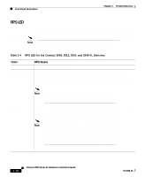
RPS LED, Color, RPS Status - configuring
 |
UPC - 746320224220
View all Cisco 3524XL manuals
Add to My Manuals
Save this manual to your list of manuals |
Page 34 highlights
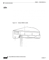
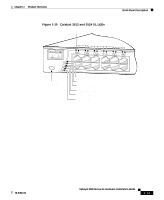
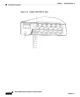
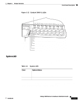
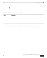
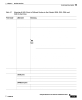
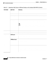
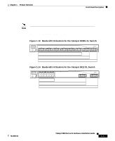
Front-Panel Description Chapter 1 Product Overview RPS LED The Redundant Power System (RPS) LED shows the RPS status. Table 1-4 and Table 1-5 list the LED colors and their meanings. Note The Cisco RPS 600 (model PWR600-AC-RPS) supports the Catalyst 3512, 3524, 3548, and 3508 XL switches. Table 1-4 RPS LED for the Catalyst 3508, 3512, 3524, and 3548 XL Switches Color Off Solid green Blinking green RPS Status RPS is off or is not installed. RPS is operational. RPS and the switch AC power supply are both powered on. If the switch power supply fails, the switch powers down and restarts after 15 seconds, using power from the RPS. The switch goes through its normal boot sequence when it restarts. Note This is not a recommended configuration. For more information see the "RPS Connector on the Catalyst 3508, 3512, 3524, and 3548 XL Switches" section on page 1-25. Amber RPS is connected but not functioning properly. One of the power supplies in the RPS could be powered down, or a fan on the RPS could have failed. Note If you are using an RPS with a revision level lower than Z3 with a Catalyst 3508G XL or a Catalyst 3548 XL switch, the switch RPS LED might display amber (normally indicating an RPS malfunction) even when the RPS is functioning properly. The LEDs display correctly for RPS revision level Z3 or later. The label on the bottom of the RPS shows the revision level. 1-16 Catalyst 3500 Series XL Hardware Installation Guide 78-6456-03
-
 1
1 -
2
-
3
-
4
-
5
-
6
-
7
-
8
-
9
-
10
-
11
-
12
-
13
-
14
-
15
-
16
-
17
-
18
-
19
-
20
-
21
-
22
-
23
-
24
-
25
-
26
-
27
-
28
-
 29
29 -
 30
30 -
 31
31 -
 32
32 -
 33
33 -
 34
34 -
 35
35 -
 36
36 -
 37
37 -
 38
38 -
 39
39 -
40
-
41
-
42
-
43
-
44
-
45
-
46
-
47
-
48
-
49
-
50
-
51
-
52
-
53
-
54
-
55
-
56
-
57
-
58
-
59
-
60
-
61
-
62
-
63
-
64
-
65
-
66
-
67
-
68
-
69
-
70
-
71
-
72
-
73
-
74
-
75
-
76
-
77
-
78
-
79
-
80
-
81
-
82
-
83
-
84
-
85
-
86
-
87
-
88
-
89
-
90
-
91
-
92
-
93
-
94
-
95
-
96
-
97
-
98
-
99
-
100
-
101
-
102
-
103
-
104
-
105
-
106
-
107
-
108
-
109
-
110
-
111
-
112
-
113
-
114
-
115
-
116
-
117
-
118
-
119
-
120
-
121
-
122
-
123
-
124
-
125
-
126
-
127
-
128
-
129
-
130
-
131
-
132
-
133
-
134
-
135
-
136
-
137
-
138
-
139
-
140
-
141
-
142
-
143
-
144
 |
 |