Cisco 3524XL Hardware Installation Guide - Page 67
Mounting the Switch in a Rack
 |
UPC - 746320224220
View all Cisco 3524XL manuals
Add to My Manuals
Save this manual to your list of manuals |
Page 67 highlights
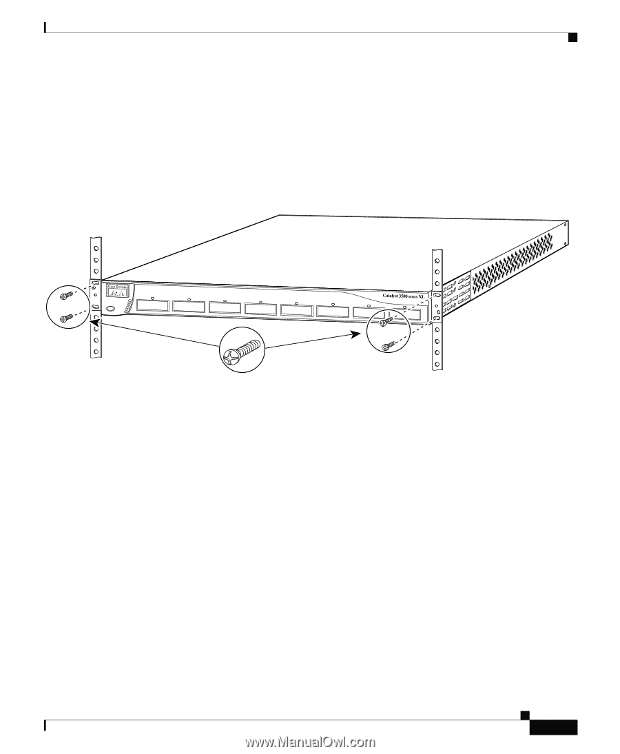
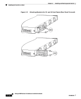
Chapter 2 Installing and Starting Up the Switch Installing the Switch in a Rack Mounting the Switch in a Rack After the brackets are attached to the switch, use the four supplied number-12 Phillips machine screws to securely attach the brackets to the rack, as shown in Figure 2-5. Figure 2-5 Mounting the Switch in a Rack 26233 1 SYSTEM 2 3 RPS 4 5 MODE STATUS 6 7 UTIL 8 DUPLX SPEED Phillips machine screws After the switch is mounted in the rack, attach the power cord to the switch. If you are using the Cisco RPS, see the Cisco RPS documentation for installation instructions. After the power is connected, the System LED turns amber for 2 seconds, and then it flashes green while the switch completes the series of POST tests described in the "Powering On the Switch and Running POST" section on page 2-15. 78-6456-03 Catalyst 3500 Series XL Hardware Installation Guide 2-11
-
 1
1 -
2
-
3
-
4
-
5
-
6
-
7
-
8
-
9
-
10
-
11
-
12
-
13
-
14
-
15
-
16
-
17
-
18
-
19
-
20
-
21
-
22
-
23
-
24
-
25
-
26
-
27
-
28
-
29
-
30
-
31
-
32
-
33
-
34
-
35
-
36
-
37
-
38
-
39
-
40
-
41
-
42
-
43
-
44
-
45
-
46
-
47
-
48
-
49
-
50
-
51
-
52
-
53
-
54
-
55
-
56
-
57
-
58
-
59
-
60
-
61
-
 62
62 -
 63
63 -
 64
64 -
 65
65 -
 66
66 -
 67
67 -
 68
68 -
 69
69 -
 70
70 -
 71
71 -
 72
72 -
73
-
74
-
75
-
76
-
77
-
78
-
79
-
80
-
81
-
82
-
83
-
84
-
85
-
86
-
87
-
88
-
89
-
90
-
91
-
92
-
93
-
94
-
95
-
96
-
97
-
98
-
99
-
100
-
101
-
102
-
103
-
104
-
105
-
106
-
107
-
108
-
109
-
110
-
111
-
112
-
113
-
114
-
115
-
116
-
117
-
118
-
119
-
120
-
121
-
122
-
123
-
124
-
125
-
126
-
127
-
128
-
129
-
130
-
131
-
132
-
133
-
134
-
135
-
136
-
137
-
138
-
139
-
140
-
141
-
142
-
143
-
144
 |
 |