Cisco 3524XL Hardware Installation Guide - Page 63
Installing the Switch in a Rack - 24
 |
UPC - 746320224220
View all Cisco 3524XL manuals
Add to My Manuals
Save this manual to your list of manuals |
Page 63 highlights
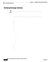
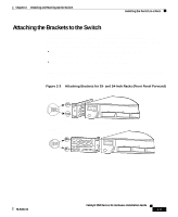
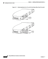
Chapter 2 Installing and Starting Up the Switch Installing the Switch in a Rack Installing the Switch in a Rack Warning To prevent bodily injury when mounting or servicing this unit in a rack, you must take special precautions to ensure that the system remains stable. The following guidelines are provided to ensure your safety: • This unit should be mounted at the bottom of the rack if it is the only unit in the rack. • When mounting this unit in a partially filled rack, load the rack from the bottom to the top with the heaviest component at the bottom of the rack. • If the rack is provided with stabilizing devices, install the stabilizers before mounting or servicing the unit in the rack. The rack-mounting brackets supplied with the switch can be attached to a 19- or 24-inch rack. Figure 2-1 shows which mounting holes attach to the rack. Note The illustrations in this section show the Catalyst 3508G XL switch as an example. Other switches in the series (Catalyst 3512, 3524, 3524-PWR, and 3548 XL) can also be installed as shown here. Figure 2-1 Bracket Mounting Points 19" rack mount point 24" rack mount point 38398 78-6456-03 19" rack mount point 24" rack mount point Catalyst 3500 Series XL Hardware Installation Guide 2-7
-
 1
1 -
2
-
3
-
4
-
5
-
6
-
7
-
8
-
9
-
10
-
11
-
12
-
13
-
14
-
15
-
16
-
17
-
18
-
19
-
20
-
21
-
22
-
23
-
24
-
25
-
26
-
27
-
28
-
29
-
30
-
31
-
32
-
33
-
34
-
35
-
36
-
37
-
38
-
39
-
40
-
41
-
42
-
43
-
44
-
45
-
46
-
47
-
48
-
49
-
50
-
51
-
52
-
53
-
54
-
55
-
56
-
57
-
 58
58 -
 59
59 -
 60
60 -
 61
61 -
 62
62 -
 63
63 -
 64
64 -
 65
65 -
 66
66 -
 67
67 -
 68
68 -
69
-
70
-
71
-
72
-
73
-
74
-
75
-
76
-
77
-
78
-
79
-
80
-
81
-
82
-
83
-
84
-
85
-
86
-
87
-
88
-
89
-
90
-
91
-
92
-
93
-
94
-
95
-
96
-
97
-
98
-
99
-
100
-
101
-
102
-
103
-
104
-
105
-
106
-
107
-
108
-
109
-
110
-
111
-
112
-
113
-
114
-
115
-
116
-
117
-
118
-
119
-
120
-
121
-
122
-
123
-
124
-
125
-
126
-
127
-
128
-
129
-
130
-
131
-
132
-
133
-
134
-
135
-
136
-
137
-
138
-
139
-
140
-
141
-
142
-
143
-
144
 |
 |