Cisco 3524XL Hardware Installation Guide - Page 68
Attaching the Optional Cable Guide
 |
UPC - 746320224220
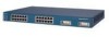
View all Cisco 3524XL manuals
Add to My Manuals
Save this manual to your list of manuals |
Page 68 highlights
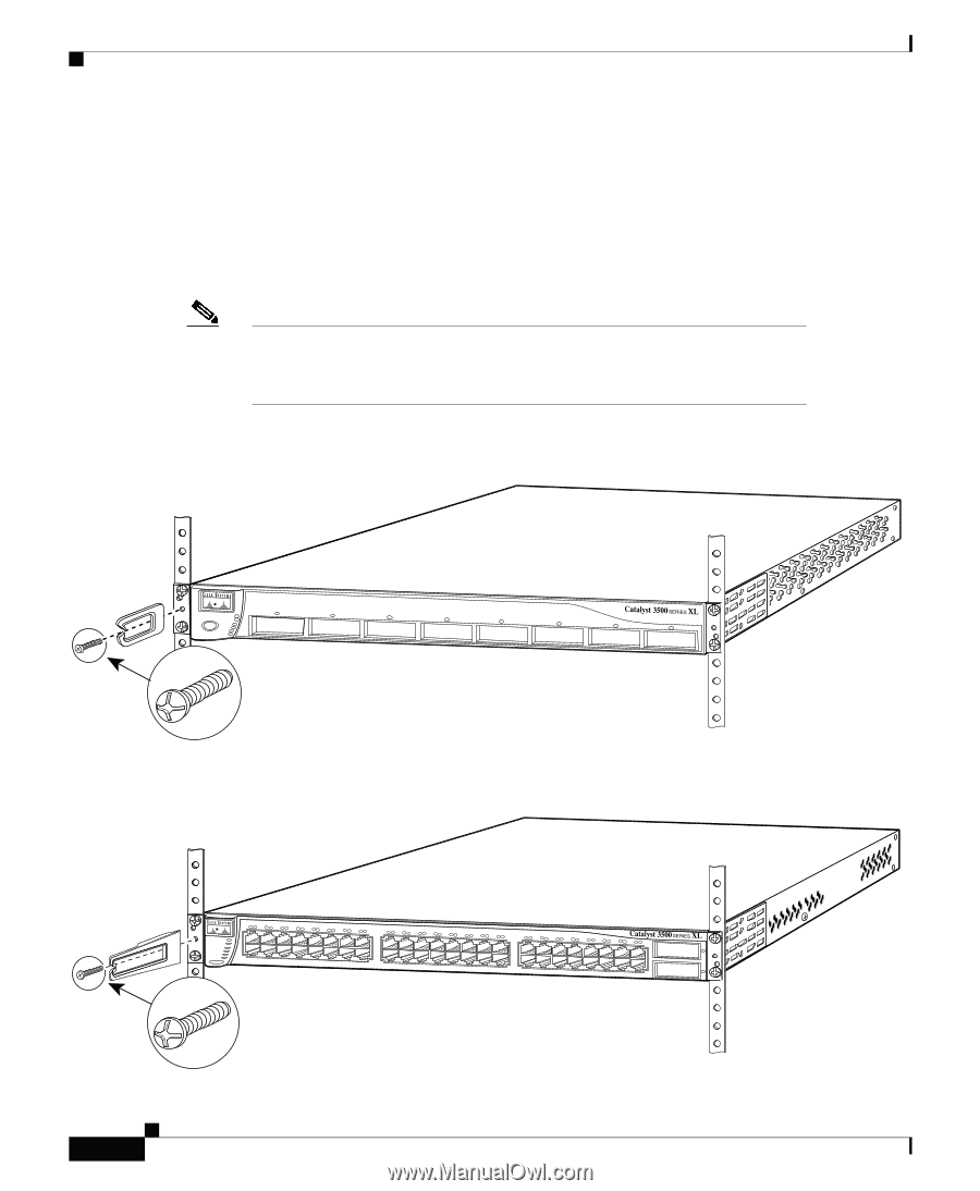
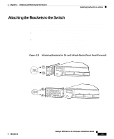
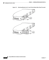
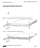
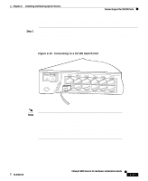
Installing the Switch in a Rack Chapter 2 Installing and Starting Up the Switch Attaching the Optional Cable Guide We recommend attaching the cable guides to prevent the cables from obscuring the front panel of the switch and the other devices installed in the rack. If the switch is in a 19-inch or 24-inch rack, use the supplied black screw, as shown in Figure 2-6, to attach the cable guide to the left or right bracket. Note The Catalyst 3548 XL switch ships with a special cable guide as shown in Figure 2-7. This cable guide secures up to 48 cables. Use the supplied black screw to mount it on the left bracket. Figure 2-6 Attaching the Cable Guide to a 3512, 3524, 3524-PWR, or 3508 XL Switch 22441 28324 1 MODE SYSTEM RPS 2 3 4 5 STATUS UTIL DUPLX SPEED 6 7 8 Cable guide screw Figure 2-7 Attaching the Cable Guide to a 3548 XL Switch SYSTEM RPS 12 1X 34 56 78 9 10 11 12 13 14 15 16 15X 17 18 17X 19 20 21 22 23 24 25 26 27 28 29 30 31 32 31X 33 34 33X 35 36 37 38 39 40 41 42 43 44 45 46 47 48 47X STATUS UTIL 1 DUPLEX SPEED 2X MODE 16X 18X 32X 34X 48X 2 Cable guide screw 2-12 Catalyst 3500 Series XL Hardware Installation Guide 78-6456-03
-
 1
1 -
2
-
3
-
4
-
5
-
6
-
7
-
8
-
9
-
10
-
11
-
12
-
13
-
14
-
15
-
16
-
17
-
18
-
19
-
20
-
21
-
22
-
23
-
24
-
25
-
26
-
27
-
28
-
29
-
30
-
31
-
32
-
33
-
34
-
35
-
36
-
37
-
38
-
39
-
40
-
41
-
42
-
43
-
44
-
45
-
46
-
47
-
48
-
49
-
50
-
51
-
52
-
53
-
54
-
55
-
56
-
57
-
58
-
59
-
60
-
61
-
62
-
 63
63 -
 64
64 -
 65
65 -
 66
66 -
 67
67 -
 68
68 -
 69
69 -
 70
70 -
 71
71 -
 72
72 -
 73
73 -
74
-
75
-
76
-
77
-
78
-
79
-
80
-
81
-
82
-
83
-
84
-
85
-
86
-
87
-
88
-
89
-
90
-
91
-
92
-
93
-
94
-
95
-
96
-
97
-
98
-
99
-
100
-
101
-
102
-
103
-
104
-
105
-
106
-
107
-
108
-
109
-
110
-
111
-
112
-
113
-
114
-
115
-
116
-
117
-
118
-
119
-
120
-
121
-
122
-
123
-
124
-
125
-
126
-
127
-
128
-
129
-
130
-
131
-
132
-
133
-
134
-
135
-
136
-
137
-
138
-
139
-
140
-
141
-
142
-
143
-
144
 |
 |