Cisco CSS11503-AC Hardware Installation Guide - Page 66
Cisco CSS11503-AC Manual
 |
View all Cisco CSS11503-AC manuals
Add to My Manuals
Save this manual to your list of manuals |
Page 66 highlights
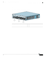
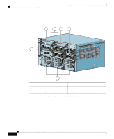
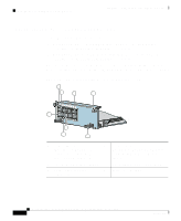
Chapter 2 Cabling the CSS 11503 and CSS 11506 Modules Cabling and Troubleshooting the CSS Figure 2-4 illustrates the SCM front panel connectors, PCMCIA slots, and LEDs. Figure 2-4 Switch Control Module Connectors and LEDs 4 3 5 6 7 11b 2 CSS5-SCM-2GE STATUS LINK/ACT MANAGEM ENT 10BASE-T DUPLEX GE 1 LINK GE 2 LINK 1 9 CONSOLE SLOT 1 SLOT 0 10 12 11a 1 2 10-Mbps half-duplex Ethernet management connector Bicolor status LED (green and red) 8 9 RJ-45 RS-232 Console connector RJ-45 RS-232 Diag connector for field service diagnostic use only. (A connector cover is provided. Removing the cover voids the warranty.) PCMCIA slot cover PCMCIA slot 0 containing a flash or hard disk PCMCIA slot 1 (shown empty) for optional installation of a second flash or hard disk Recessed button (reserved for field service use only) 3 4 5 Amber status LED Link/Act LED Duplex LED 10 11a 11b 6 7 LC-type SFP GBIC (one of two) 12 Link LED for the associated SFP GBIC on the left Cisco 11500 Series Content Services Switch Hardware Installation Guide 2-12 System Control 78993 PCMCIA 8 78-13884-06
-
 1
1 -
2
-
3
-
4
-
5
-
6
-
7
-
8
-
9
-
10
-
11
-
12
-
13
-
14
-
15
-
16
-
17
-
18
-
19
-
20
-
21
-
22
-
23
-
24
-
25
-
26
-
27
-
28
-
29
-
30
-
31
-
32
-
33
-
34
-
35
-
36
-
37
-
38
-
39
-
40
-
41
-
42
-
43
-
44
-
45
-
46
-
47
-
48
-
49
-
50
-
51
-
52
-
53
-
54
-
55
-
56
-
57
-
58
-
59
-
60
-
 61
61 -
 62
62 -
 63
63 -
 64
64 -
 65
65 -
 66
66 -
 67
67 -
 68
68 -
 69
69 -
 70
70 -
 71
71 -
72
-
73
-
74
-
75
-
76
-
77
-
78
-
79
-
80
-
81
-
82
-
83
-
84
-
85
-
86
-
87
-
88
-
89
-
90
-
91
-
92
-
93
-
94
-
95
-
96
-
97
-
98
-
99
-
100
-
101
-
102
-
103
-
104
-
105
-
106
-
107
-
108
-
109
-
110
-
111
-
112
-
113
-
114
-
115
-
116
-
117
-
118
-
119
-
120
-
121
-
122
-
123
-
124
-
125
-
126
-
127
-
128
-
129
-
130
-
131
-
132
-
133
-
134
-
135
-
136
-
137
-
138
-
139
-
140
-
141
-
142
-
143
-
144
-
145
-
146
-
147
-
148
-
149
-
150
-
151
-
152
-
153
-
154
-
155
-
156
-
157
-
158
-
159
-
160
-
161
-
162
-
163
-
164
-
165
-
166
-
167
-
168
-
169
-
170
-
171
-
172
-
173
-
174
-
175
-
176
-
177
-
178
-
179
-
180
-
181
-
182
-
183
-
184
 |
 |
