Craftsman 28913 Operation Manual - Page 26
<4::7
 |
View all Craftsman 28913 manuals
Add to My Manuals
Save this manual to your list of manuals |
Page 26 highlights
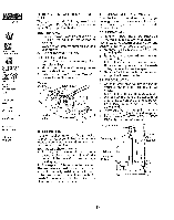
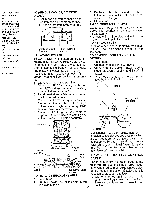
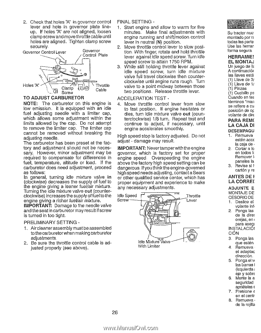
2. Check that holes '7_' in governor control lever and hole in governor plate line- up. if holes '_' are not aligned, loosen clamp screw and move throttle cable until holes are aligned. Tighten clamp screw securely. Governor Control Lever Governor Control Plate
-
 1
1 -
2
-
3
-
4
-
5
-
6
-
7
-
8
-
9
-
10
-
11
-
12
-
13
-
14
-
15
-
16
-
17
-
18
-
19
-
20
-
 21
21 -
 22
22 -
 23
23 -
 24
24 -
 25
25 -
 26
26 -
 27
27 -
 28
28 -
 29
29 -
 30
30 -
 31
31 -
32
-
33
-
34
-
35
-
36
-
37
-
38
-
39
-
40
-
41
-
42
-
43
-
44
-
45
-
46
-
47
-
48
-
49
-
50
-
51
-
52
-
53
-
54
-
55
-
56
-
57
-
58
-
59
-
60
-
61
-
62
-
63
-
64
 |
 |
2.
Check
that
holes
'7_' in governor
control
lever
and
hole
in
governor
plate
line-
up.
if holes
'_'
are not aligned,
loosen
clamp
screw
and move throttle
cable until
holes
are aligned.
Tighten
clamp
screw
securely.
Governor Control Lever
Governor
Control
Plate
<4::7
o
Holes '_' _:.
_hrottle
[
_.,
Clamp
UU1L_j)
_M_,
"-- 1_]
Screw
_
.....
TO
ADJUST
CARBURETOR
NOTE:
The
carburetor
on this
engine
is
low
emissiom
It is equipped
with
an
idle
fuel
adjusting
needle
with
a
limiter
cap,
which
allows
some
adjustment
within
the
limits
allowed
by the
cap.
Do
not attempt
to
remove
the limiter
cap.
The
limiter
cap
cannot
be
removed
without
breaking
the
adjusting
needle.
The
carburetor
has
been
preset
at the fac-
tory
and
adjustment
should
not
be neces-
sary.
However,
minor
adjustment
may
be
required
to
compensate
for
differences
in
fuel,
temperature,
altitude
or
load.
If the
carburetor
does
need
adjustment,
proceed
as follows:
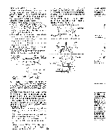
In
general,
turning
idle
mixture
valve
in
(clockwise)
decreases
the supply
of fuel
to
the
engine
giving
a leaner
fuel/air
mixture.
Turning
the idle mixture
valve
out
(counter-
clockwise)
increases
the supply
offuel
to the
engine
giving
a richer
fuel/air
mixture.
IMPORTANT:
Damage
to the needle
valve
and the seat in carburetor
may result
if screw
is turned
in too tight.
PRELIMINARY
SETTING
-
1.
Air cleaner
assembly
must be assembled
to the carburetor
when
making
carburetor
adjustment&
2,
Be sure
the throttle
control
cable
is ad-
justed
properly
(see
above).
FINAL
SETTING
-
1.
Start
engine
and
allow
to warm
for
five
minutes.
Make
final
adjustments
with
engine
running
and
shift/motion
control
lever
in neutral
(N)
position,
2.
Move
throttle
control
lever
to slow
posi-
tion.
With
finger,
rotate
and
hold throttle
lever
against
idle speed
screw.
lParn idle
speed
screw
to attain
1750
RPM.
3_ While
still
holding
throttle
lever
against
idle
speed
screw,
turn
idle
mixture
valve
full
travel
clockwise
then
counter-
clockwise
until
engine
runs
rough
Turn
valve
to
a point
midway
between
those
two positions.
Release
throttle
lever,
ACCELERATION
TEST
4,
Move
throttle
control
lever
from
slow
to fast
position.
If engine
hesitates
or
dies,
turn
idle
mixture
valve
out
(coun-
terclockwise)
1/8 turn.
Repeat
test
and
continue
to
adjust,
if
necessary,
until
engine
accelerates
smoothly.
High
speed
stop is factory
adjusted.
Do not
adjust
- damage
may
resulL
IMPORTANT:
Never
tamperwith
the engine
governor,
which
is
factory
set
for
proper
engine
speed.
Overspeeding
the
engine
above
the factory
high speed
setting
can be
dangerous_
Ifyou thinkthe
engine-governed
high speed
needs
adjusting,
contact
a Sears
or other
qualified
service
center,
which
has
proper
equipment
and
experience
to
make
any necessary
adjustments.
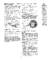
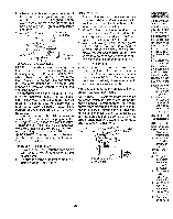
Idle Speed
F
_f_--_"-_"""
Throttle
Screw--_
'Lever
C
Idle Mixture Valve
/
_
With Umiter
26
Su tractor nue'
montado por r_
todas las parte
Use las herran
forma segura,
HI=RRAMIEI
E1 MONTAJ
Un juego de i1_
A continuaci6r
tas llaves est&
(1) Llave de 3/
(1) Llave de t/
(!)
Pinzas
(I)
Cuchi]lo pa
Cuando en tee
t6rminos
"man
se
refiere
a cu
posici6n de oi:
volante de dire
PARA
REM(
LA CAJA
DI
DESEMPAQU
1o Remueva
est6n accE
la caja de,
2,
Cortar a Io
en todos k
Remover
I,
paneles la
3.
Revise si i"
cart6n y re
ANTES
DE
!
LA
CORREr
ADJUNTE
E
MONTAJE DE
CESORIO DE
1.
Deslice el
votante inf,
2.
Ponga fas
de la dire[
orejas, en
para asegl
INSTALACIOI
OlON
3_
Ponga las
que est6n
4o
Remueva
el adaptac
direcci6no
5.
Pongaelw
las barras I
(izquierda
eje y sobr_
6.
Monte la a
seguridad
apri_telas E
7.
Presione
en el centr
8.
Remueva,
de la rejilla