D-Link DFL-1100 Product Manual
D-Link DFL-1100 - Security Appliance Manual
 |
UPC - 790069270239
View all D-Link DFL-1100 manuals
Add to My Manuals
Save this manual to your list of manuals |
D-Link DFL-1100 manual content summary:
- D-Link DFL-1100 | Product Manual - Page 1
D-Link DFL-1100 TM Network Security Firewall Manual Building Networks for People (04/19/2005) - D-Link DFL-1100 | Product Manual - Page 2
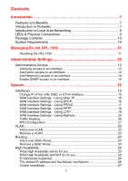
Firewalls 7 Introduction to Local Area Networking 8 LEDs & Physical Connections 9 Package Contents 10 System Requirements 10 Managing D-Link DFL-1100 11 Resetting the DFL-1100 Using PPTP 18 WAN Interface Settings - Using L2TP 19 WAN Interface Settings - Using BigPond 20 Traffic Shaping 20 - D-Link DFL-1100 | Product Manual - Page 3
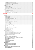
33 Using NTP to sync time 33 Setting time and date manually 33 Firewall 34 Policy 34 Policy modes 34 Action Types 34 Source and Destination Filter 35 Service Filter 35 Schedule ...35 Intrusion Detection / Prevention 36 Traffic Shaping 36 Policy Routing 36 Add a new policy 37 Change order - D-Link DFL-1100 | Product Manual - Page 4
56 L2TP/PPTP Clients 57 L2TP/PPTP Servers 58 IPSec VPN between two networks 59 Creating a LAN-to-LAN IPSec VPN Tunnel 59 VPN between client and an internal network 60 Creating a Roaming Users IPSec Tunnel 60 Adding an L2TP/PPTP VPN Client 61 Adding an L2TP/PPTP VPN Server 61 VPN - Advanced - D-Link DFL-1100 | Product Manual - Page 5
the DFL-1100's Configuration 73 Restoring the DFL-1100's Configuration 73 Restart/Reset 74 Restoring system settings to factory defaults 75 Upgrade 76 Upgrade Firmware 76 Upgrade IDS Signature-database 76 Status 77 System 77 Interfaces 78 VPN...79 Connections 80 DHCP Server 81 Users 81 - D-Link DFL-1100 | Product Manual - Page 6
Settings for Main office 113 Windows XP client and L2TP server 116 Settings for the Windows XP client 116 Settings for Main office 118 Intrusion Detection and Prevention 120 Appendixes 123 Appendix A: ICMP Types and Codes 123 Appendix B: Common IP Protocol Numbers 125 - D-Link DFL-1100 | Product Manual - Page 7
over Firewall and VPN sessions. VPN Server/Client Supported Supports IPSec LAN-to-LAN or Roaming user tunnels with AES encryption in addition to PPTP and IPSec over L2TP Content Filtering Strip ActiveX objects, Java Applets, JavaScript, and VBScript from HTTP traffic Bandwidth Management DFL-1100 - D-Link DFL-1100 | Product Manual - Page 8
10/100Mbps network card, or a wireless network card. Most networks use hardware devices such as hubs or switches that each cable can be connected port for a specific piece of data. A switch minimizes network traffic overhead and speeds up the communication over a network. Networks take some - D-Link DFL-1100 | Product Manual - Page 9
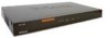
this port to connect to a Fast Ethernet Switch to service more than 1 client PC on the internal office network. DMZ Port: Use this port to service an additional physically segmented Private or Transparent Network to be occupied by WAN accessible servers (FTP, HTTP, DNS). DC Power (on rear of unit - D-Link DFL-1100 | Product Manual - Page 10
Package Contents Contents of Package: • D-Link DFL-1100 Firewall • Manual and CD • Installation Guide • PC Power cable • Straight-through CAT-5 cable • RS-232 Null Modem Cable If any of the above items are missing, please contact your reseller. System - D-Link DFL-1100 | Product Manual - Page 11
Managing D-Link DFL-1100 When a change is made to the resetting the DFL-1100 to factory default settings for more information. After the reset procedure has been carried out the DFL-1100 will be configured at factory default settings, with a LAN IP address of 192.168.1.1. Connect to the firewall - D-Link DFL-1100 | Product Manual - Page 12
Access Management UI Ports - The ports for the DFL-1100's Web Server Management UI (HTTP and HTTPS) can be customized if so desired. These values must change if User Authentication is enabled (User Authentication uses 80 and 443 to accomplish user login). Ping - If enabled, it specifies who can - D-Link DFL-1100 | Product Manual - Page 13
SNMP - Specifies if SNMP should or should not be allowed on the interface. The DFL1100 only supports would like to add it to. Only users with administrative rights can login on interfaces Step 4. Specify protocol to be used to access the DFL-1100 via the dropdown menu. Select HTTP and HTTPS (Secure - D-Link DFL-1100 | Product Manual - Page 14
have read-only access enabled on an interface, all users will only have read-only access, even if they SNMP traps, for example 192.168.1.0/24 for a whole class C network or 172.16.0.1 - 172.16.0.10 for a range of IP addresses. Step 4. Specify the community string used to authenticate the DFL-1100 - D-Link DFL-1100 | Product Manual - Page 15
IP. If the computer through which the DFL-1100 is being configured is a DHCP client, you will need to manually release and renew the IP address after applying changes and restarting. Failure to follow these directions will result in the firewall configuration reverting back to the state prior to - D-Link DFL-1100 | Product Manual - Page 16
to you by your ISP. All fields are required except the Secondary DNS Server. Note: Do not use the numbers displayed in these fields, they the WAN interface. This is the address that may be used to ping the firewall, remotely control it, and be used as the source address for dynamically translated - D-Link DFL-1100 | Product Manual - Page 17
PPPoE Use the following procedure to configure the DFL-1100 external interface to use PPPoE (Point-to-Point your ISP. • Service Name - When using PPPoE some ISPs require you to fill in a Service Name. • Primary and Secondary DNS Server - The IP addresses of your DNS servers; these are optional - D-Link DFL-1100 | Product Manual - Page 18
The login or username supplied to you by your ISP. • Password - The password supplied to you by your ISP. • PPTP Server IP - The IP of the PPTP server that the DFL-1100 will connect to. Before PPTP can be used to connect to your ISP, the physical (WAN) interface parameters must be input. You can use - D-Link DFL-1100 | Product Manual - Page 19
• Username - The login or username supplied to you by your ISP. • Password - The password supplied to you by your ISP. • L2TP Server IP - The IP of the L2TP server that the DFL-1100 will connect to. Before L2TP can be used to connect to your ISP, the physical (WAN) interface parameters must be input - D-Link DFL-1100 | Product Manual - Page 20
of data are moving through the DFL-1100. For example, the policy for the web server might be given higher priority than the policies for most employees' computers. You can use traffic shaping to guarantee the amount of bandwidth available through the firewall for a policy. Guarantee bandwidth to - D-Link DFL-1100 | Product Manual - Page 21
its external interface. Ideally, you want this MTU to be the same as the smallest MTU of all the networks between the DFL-1100 and the Internet. If the packets the DFL-1100 sends are larger, they get broken up or fragmented, which could slow down transmission speeds. Trial and error is the only - D-Link DFL-1100 | Product Manual - Page 22
801.2Q VLAN ID. Step 5. Fill in the IP address of the VLAN interface. This is the address that will be used to ping the firewall, remotely control it and use as gateway for hosts on that VLAN. Step 6. Choose the correct Subnet mask of this interface from the drop down - D-Link DFL-1100 | Product Manual - Page 23
section describes the firewall's routing table. The DFL-1100 uses a slightly different method of describing routes compared to most other systems. However, we believe that this method of describing routes is easier to understand, making it less likely for users VPN tunnel. - D-Link DFL-1100 | Product Manual - Page 24
Add a new Static Route Follow these steps to add a new route. Step 1. Go to System and Routing. Step 2. Click on Add new in the bottom of the routing table. Step 3. Choose the interface that the route should be sent through from the dropdown menu. Step 4. Specify the Network and Subnet mask. Step 5. - D-Link DFL-1100 | Product Manual - Page 25
Clients connecting through the firewall to your firewall setup will firewalls supporting stateful failover, the D-Link High Availability will only work between two D-Link DFL-1100 Firewalls. As the internal workings of different firewalls, and, indeed, different major versions of the same firewall - D-Link DFL-1100 | Product Manual - Page 26
traffic flowing through the cluster; if either firewall is inoperative, the associated IP address will simply be unreachable. • One "virtual" IP address; shared between the firewalls , will be answered by the active firewall. The hardware address of the shared IP address, and other published addresses for that - D-Link DFL-1100 | Product Manual - Page 27
the Ethernet multicast address corresponding to the shared hardware address, i.e. 11-00-00-C1-4A-nn. Link-level multicasts were chosen over normal unicast packets between the nodes using the synchronization connection. When the active firewall ceases to function, for whatever reason and for even a - D-Link DFL-1100 | Product Manual - Page 28
Setting up a High Availability cluster First of all, each of the DFL-1100 Firewalls must be setup so far that one can manage them over the web interface. In this example the two units are configured as follow, the master DFL-1100 will be configured with 192.168.1.2 on its internal interface, and the - D-Link DFL-1100 | Product Manual - Page 29
Now login to the slave firewall and click on System in the menu bar, and then click HA below it; in this screen you will click on Receive configuration from first - D-Link DFL-1100 | Product Manual - Page 30
then click Logging below it. Logging, the ability to audit decisions made by the firewall, is a vital part in all network security products. The D-Link DFL-1100 provides several options for logging activity. The DLink DFL-1100 logs activity by sending the log data to one or two log receivers in the - D-Link DFL-1100 | Product Manual - Page 31
D-Link DFL-1100 discard changes. Enable Audit Logging To start auditing all traffic through the firewall, follow the steps below. This is required when running the sensitivity level. Step 3. In the SMTP Server field, fill in the SMTP server to which the DFL-1100 will send the e-mail alerts. Step 4. - D-Link DFL-1100 | Product Manual - Page 32
Time Click on System in the menu bar, and then click Time below it. This will give you the option to either set the system time by synchronizing with an Internet Network Time Server (NTP) or by entering the system time manually. 32 - D-Link DFL-1100 | Product Manual - Page 33
the Enable NTP box. Step 2. Enter the Server IP Address or Server name with which you want to synchronize. Click the Apply button below to apply the settings or click Cancel to discard changes. Setting time and date manually Follow these steps to manually set the system time. Step 1. Check the - D-Link DFL-1100 | Product Manual - Page 34
traffic through the firewall. The policies also regulate how bandwidth management, traffic shaping, is applied to traffic flowing through the WAN interface of the firewall firewall. The firewall can run in NAT or No NAT (Route) mode. Select NAT mode to use DFL-1100 networks from users on the Internet - D-Link DFL-1100 | Product Manual - Page 35
by a comma (,) or write Any for any authenticated user. If it is left blank there is no need for authentication for the policy. Service Filter Either choose a predefined service from the dropdown menu or make a custom service. The following custom services exist: All - Matches all protocols. TCP+UDP - D-Link DFL-1100 | Product Manual - Page 36
the traffic, and if the DFL-1100 detects anything it will log, e-mail an alert (if configured), and pass on the traffic. If Prevention is used the traffic will be dropped and logged and if configured, an e-mail alert will be sent. Traffic Shaping The simplest way to obtain quality of service in - D-Link DFL-1100 | Product Manual - Page 37
for no scheduling. Step 4. If using Traffic shaping, fill in the required information. If not, skip this step. Click the Apply button below to apply the changes or click Cancel to discard changes. Note: Refer to Appendix C of the manual for details on mapping Public IP addresses to Internal Servers. - D-Link DFL-1100 | Product Manual - Page 38
change the order from the available policy lists. Step 2. Click on the Edit link corresponding to the rule you want to move. Step 3. Change the number in policy in from the available policy lists. Step 2. Click on the Edit link corresponding to the rule you want to delete. Step 3. Enable the Delete - D-Link DFL-1100 | Product Manual - Page 39
Follow these steps to configure IDP on a policy. Step 1. Choose the policy you would like have IDP on. Step 2. Click on the Edit link corresponding to the rule you want to configure. Step 3. Enable the Intrusion Detection / Prevention checkbox. Step 4. Choose Prevention from the mode drop down - D-Link DFL-1100 | Product Manual - Page 40
the WAN. One may also regulate how bandwidth management (traffic shaping) is applied to traffic flowing through the WAN interface of the firewall to the LAN or DMZ. It is also possible to use Intrusion Detection / Prevention on Port mapped services. These are applied in the same way as with policies - D-Link DFL-1100 | Product Manual - Page 41
to delete a mapping. Step 1. Choose the mapping list (WAN, LAN, or DMZ) you would like do delete the mapping from. Step 2. Click on the Edit link corresponding to the rule you want to delete. Step 3. Enable the Delete mapping checkbox. Click the Apply button below to apply the changes or click - D-Link DFL-1100 | Product Manual - Page 42
on Firewall in the menu bar, and then click Users below it. This will show all the users, and the first section is the administrative users. The first column shows the access levels, Administrator and Read-only. An Administrator user can add, edit and remove rules, change settings of the DFL-1100 - D-Link DFL-1100 | Product Manual - Page 43
and change all settings. • Read-only - the user can only look at the configuration of the firewall. • No Admin Access - The user is only used for user authentication. Follow these steps to change Administrative User Access level. Step 1. Click on the user you would like to change level of. Step - D-Link DFL-1100 | Product Manual - Page 44
steps to delete an Administrative User. Step 1. Click on the user you would like to delete. Step 2. Enable the Delete user checkbox. Click the Apply button below to apply the setting or click Cancel to discard changes. Note: Deleting a user is irreversible; once the user is deleted, it cannot be - D-Link DFL-1100 | Product Manual - Page 45
, either by itself or as a front-end to other authentication services. The DFL-1100 RADIUS Support The DFL-1100 can use RADIUS to verify users against, for example, Active Directory or Unix password-file. It is possible to configure up to two servers, if the first one is down it will try the second - D-Link DFL-1100 | Product Manual - Page 46
the firewall. Step 4. Choose new ports for the web-based management GUI to listen on since enabling user authentication requires the default ports for user login purposes (80 and 443). Click the Apply button below to apply the settings or click Cancel to discard changes. Enable RADIUS Support Follow - D-Link DFL-1100 | Product Manual - Page 47
the Apply button below to apply the settings or click Cancel to discard changes. Note: The user name and password should be at least six characters long. The user name and password can contain numbers (0-9) and upper and lower case letters (A-Z, az). Special characters and spaces are not allowed - D-Link DFL-1100 | Product Manual - Page 48
. Follow these steps to delete a user. Step 1. Click on the user you would like to delete. Step 2. Enable the Delete user checkbox. Click the Apply button below to apply the settings or click Cancel to discard changes. Note: Deleting a user is irreversible; once the user is deleted, it cannot be - D-Link DFL-1100 | Product Manual - Page 49
. The DFL-1100 can be configured to have a start time and stop time, as well as 2 different time periods in a day. For example, an organization may only want the firewall to allow the internal network users to access the Internet during work hours. Therefore, one may create a schedule to allow - D-Link DFL-1100 | Product Manual - Page 50
Add new one-time schedule Follow these steps to create and add a new one-time schedule. Step 1. Go to Firewall and Schedules and choose Add new. Step 2. Choose the starting and ending date and hour when the schedule should be active. Step 3. Use the checkboxes - D-Link DFL-1100 | Product Manual - Page 51
in the range 1024-65535, will match this service. Follow these steps to add a TCP, UDP, or TCP/UDP service. Step 1. Go to Firewall and Service and choose add new. Step 2. Enter a Name for the service in the name field. This name will appear in the service list when you add a new policy. The name - D-Link DFL-1100 | Product Manual - Page 52
can be grouped in order to simplify configuration. Consider a Web server using standard http as well as SSL encrypted http (https). Instead of having to create two separate rules allowing both types of services through the firewall, a service group named, for instance, Web, can be created, with the - D-Link DFL-1100 | Product Manual - Page 53
solve this problem, the DFL-1100 can be instructed to pass an ICMP error message only if it is related to an existing connection. Check this option to enable this feature for connections using this service. ALG - Similar to the way most stateful inspection firewalls behave, the DFL-1100 filters only - D-Link DFL-1100 | Product Manual - Page 54
of the DFL-1100, is made up of two basic parts: • Internet Key Exchange security protocol (IKE) • IPSec protocol (ESP) The first part, IKE, is the initial negotiation phase, where the two VPN endpoints agree on which methods will be used to provide security for the underlying IP traffic. Furthermore - D-Link DFL-1100 | Product Manual - Page 55
Protocols (LCP) to negotiate parameters, test and establish the link. • Network Control Protocol (NCP) to establish and negotiate different network layer protocols (DFL-1100 only supports IP) • Data encapsulation to encapsulate datagram's over the link. To establish a PPP tunnel, both sides send LCP - D-Link DFL-1100 | Product Manual - Page 56
to a challenge issued by the DFL-1100. CHAP is superior to PAP in that the password is never sent over the link. Instead the password is used to not backwards compatible with MS-CHAP v1. Both the Remote Access Server and the client must prove they have knowledge of the password via two-way Challenge - D-Link DFL-1100 | Product Manual - Page 57
PPTP/L2TP Client tunnel. Interface IP - Specifies if the L2TP/PPTP Client tunnel should use a Static IP or obtain a dynamic IP from the server. Remote Gateway - The IP address of the remote PPTP/L2TP Server with PPTP). A selection of None means that data will be sent over the PPP link unencrypted. - D-Link DFL-1100 | Product Manual - Page 58
VPN tunnel. Leave this field Blank for the LAN IP. IP Pool and settings - Information related to client IP assignment. Client IP Pool - An IP range, group or entire network that the PPTP/L2TP Server Service (WINS) servers that are used in Microsoft environments which uses the NetBIOS Name Servers - D-Link DFL-1100 | Product Manual - Page 59
place in an encrypted IPSec VPN tunnel that connects the two DFL-1100 NetDefend Firewalls across the Internet. Users on the internal networks are not aware that when they connect to a computer on the other network that the connection runs across the Internet. DFL-1100 Firewall As shown in the - D-Link DFL-1100 | Product Manual - Page 60
and the internal network takes place in an encrypted VPN tunnel that connects the DFL-1100 and the roaming users across the Internet. DFL-1100 Firewall The example shows a VPN between a roaming VPN client and the internal network, but you can also create a VPN tunnel that uses the DMZ network. The - D-Link DFL-1100 | Product Manual - Page 61
Cancel to discard changes. Adding an L2TP/PPTP VPN Server Follow these steps to add an L2TP or PPTP VPN Server configuration that listens on the WAN IP. Step 1. Go to Firewall and VPN and choose Add new PPTP server or Add new L2TP server in the L2TP/PPTP Server section. Step 2. Enter a Name for this - D-Link DFL-1100 | Product Manual - Page 62
a NAT device. On if supported - Always tries to use NAT-T when setting up the tunnel. Keepalives No keepalives - Keep-alive is disabled. Automatic keepalives - The firewall will send ICMP pings to IP Addresses automatically discovered from the VPN Tunnel settings. Manually configured IP addresses - D-Link DFL-1100 | Product Manual - Page 63
proposal is the starting point for the negotiation. A proposal defines encryption parameters, for instance encryption algorithm, life times etc, that the VPN gateway supports. There are two types of proposals, IKE proposals and IPSec proposals. IKE proposals are used during IKE Phase-1 (IKE Security - D-Link DFL-1100 | Product Manual - Page 64
. It links an identity to a public key in a trustworthy manner. Certificates can be used to authenticate individual users or other entities. These types of certificates are commonly called end-entity certificates. Before a VPN tunnel with certificate based authentication can be set up, the firewall - D-Link DFL-1100 | Product Manual - Page 65
list can be selected in the Identity List field on the VPN page. If an Identity List is configured, the firewall will match the identity of the connecting remote peer against the Identity List, and only allow it to open the VPN tunnel if it matches the contents of the list. If no - D-Link DFL-1100 | Product Manual - Page 66
the requested URL and the URL Blacklist the DFL-1100 will block the Web page. You can configure URL filtering to work, all HTTP traffic needs to go through a policy using a service with the HTTP ALG. Content remove a URL. Step 1. Navigate to Firewall / Content Filtering and choose Edit global URL - D-Link DFL-1100 | Product Manual - Page 67
steps to add or remove a URL. Step 1. Navigate to Firewall / Content Filtering and choose Edit global URL Blacklist. Step 2. cookies. Note: For HTTP URL filtering to work, all HTTP traffic needs to go through a policy using a service with the HTTP ALG. A pre-defined "HTTP-outbound TCP: All -> 80 - D-Link DFL-1100 | Product Manual - Page 68
; these are: • IP address • Netmask • Subnet • Gateway address • DNS Servers • WINS Servers • Domain name The DFL-1100 DHCP Server assigns and manages IP addresses from specified address pools within the firewall to the DHCP clients. Note: Leases are remembered over a re-configure or reboot of the - D-Link DFL-1100 | Product Manual - Page 69
the DNS Relay function is configured, the DHCP server will assign those addresses. Step 5. Optionally type in the WINS servers the DHCP server will assign to the clients. Step 6. Optionally type in the domain that the DHCP server will assign to the clients. Step 7. Choose the length of time the DHCP - D-Link DFL-1100 | Product Manual - Page 70
in the menu bar, and then click DNS Relay below it. The DFL-1100 contains a DNS Relay function that can be configured to relay DNS queries from the internal LAN to the DNS servers used by the firewall itself. Enable DNS Relayer Follow these steps to enable the DNS Relayer. Step 1. Enable by checking - D-Link DFL-1100 | Product Manual - Page 71
than one per second. This method is the best suited for diagnosing connectivity problems. • IP Address - Target IP to send the ICMP Echo Requests to. 168.10.1 the Number of packets is five. After clicking on Apply the firewall will start to send the ICMP Echo Requests to the specified IP. After - D-Link DFL-1100 | Product Manual - Page 72
, the IP address in Dynamic DNS Server will be automatically updated with the new IP address provided by ISP. Click DynDNS in the Tools menu to enter Dynamic DNS configuration. The firewall provides a list of a few predefined DynDNS service providers. Users must register with one of these providers - D-Link DFL-1100 | Product Manual - Page 73
system settings, IP addresses of the firewall's network interfaces, address table, service table, IPSec settings, port mapping, . System Administrators can restore the firewall's configuration file with the one stored on disc. Exporting the DFL-1100's Configuration Follow these steps to - D-Link DFL-1100 | Product Manual - Page 74
Restart/Reset Restarting the DFL-1100 Follow these steps to restart the DFL-1100. Step 1. Choose if you want to do a quick or full restart. Step 2. Click Restart Unit and the unit will restart. 74 - D-Link DFL-1100 | Product Manual - Page 75
firmware file available for upload to the device in the case where the firmware version is defaulted to an older version. The factory reset procedure erases all configuration changes that have been made to the DFL-1100 Flow Control. Step 2. Power Cycle the Firewall by either using the power switch on - D-Link DFL-1100 | Product Manual - Page 76
Firmware To upgrade the firmware of the DFL-1100, obtain the latest version from support.dlink.com (US). Make sure the firmware file is stored on the PC connected to the firewall signatures from D-Link. After downloading the newest version of the software, connect to the firewall's Web-based - D-Link DFL-1100 | Product Manual - Page 77
DFL-1100 displays the status information about the Firewall. Administrator may use the Status section to check the System Status, Interface statistics, VPN status, IP connections, and DHCP Servers the originating IP. Firmware version - The firmware version running on the firewall. Last restart - The - D-Link DFL-1100 | Product Manual - Page 78
below it. A window will appear providing information about the interfaces on the DFL-1100. By default, information about the LAN interface will be displayed. To see information for a specific interface, click on the respective link. Interface - Name of the interface shown, LAN, WAN, or DMZ - D-Link DFL-1100 | Product Manual - Page 79
then click Interfaces below it. A window will appear providing information about the VPN connections on the DFL-1100. By default information about the first VPN tunnel will be displayed. To see another one, click on that VPN tunnels name. The two graphs display the send and receive rate through the - D-Link DFL-1100 | Product Manual - Page 80
providing information about the content of the state table. The state table shows the last 100 connections opened through the firewall. Connections are created when traffic is permitted to pass via the policies. Each connection has two timeout values, one in each direction. These are updated - D-Link DFL-1100 | Product Manual - Page 81
to DHCP clients. Active leases are the current computers using this DHCP server. It is Users below it. A window will appear providing user information. Currently authenticated users - users logged in using HTTP/HTTPS authentication, users logged in on PPTP and L2TP servers will be listed here. Users - D-Link DFL-1100 | Product Manual - Page 82
SYSLog recipient works. SYSLog daemons on UNIX servers usually log to text files, line by provide statistical information regarding connections and amount of traffic. Example: Oct 20 2003 09:45: the firewall when the usage log was sent. The value after "tp" is the throughput through the firewall at - D-Link DFL-1100 | Product Manual - Page 83
connsrcport=3179 conndestif=wan conndestip=64.7.210.132 conndestport=80 In this line, traffic from 192.168.0.10 on the LAN interface is connecting to 64.7.210.132 on port 80 on the WAN side of the firewall (internet). Another event is generated when the connection is closed. The information included - D-Link DFL-1100 | Product Manual - Page 84
and keys should be chosen making use of symbols, letters, and numbers to decrease the likelihood of a brute force dictionary attack success. In these guides for example Firewall->Users will mean that the Firewall tab should first be selected from the menu at the top of the screen, followed by the - D-Link DFL-1100 | Product Manual - Page 85
using IPSec Settings for Branch office 1. Setup interfaces, System->Interfaces: WAN IP: 194.0.2.10 LAN IP: 192.168.4.1, Subnet mask: 255.255.255.0 2. Setup IPSec tunnel, Firewall->VPN: Under IPSec tunnels click Add new Name the tunnel ToMainOffice Local net: 192.168.4.0/24 PSK: 1234567890 (Do not - D-Link DFL-1100 | Product Manual - Page 86
Remote Gateway: 194.0.2.20 Enable Automatically add a route for the remote network Click Apply 3. Setup policies for the new tunnel, Firewall->Policy: Click Global policy parameters Enable Allow all VPN traffic: internal->VPN, VPN->internal and VPN->VPN Click Apply 4. Click Activate and wait for the - D-Link DFL-1100 | Product Manual - Page 87
, System->Interfaces: WAN IP: 194.0.2.20 LAN IP: 192.168.1.1, Subnet mask: 255.255.255.0 2. Setup IPSec tunnel, Firewall->VPN: Under IPSec tunnels click add new Name the tunnel ToBranchOffice Local net: 192.168.1.0/24 PSK: 1234567890 (Note! You should use a key that is hard - D-Link DFL-1100 | Product Manual - Page 88
Allow all VPN traffic: internal->VPN, VPN->internal and VPN->VPN Click Apply 4. Click Activate and wait for the firewall to restart This example will allow all traffic between the two offices. To get a more secure solution read the A more secure LAN-to-LAN VPN solution section of this user guide. 88 - D-Link DFL-1100 | Product Manual - Page 89
LAN-to-LAN VPN using PPTP Settings for Branch office 1. Setup interfaces, System->Interfaces: WAN IP: 194.0.2.10 LAN IP: 192.168.4.1, Subnet mask: 255.255.255.0 2. Setup PPTP client, Firewall->VPN: Under PPTP/L2TP clients click Add new PPTP client Name the tunnel toMainOffice - D-Link DFL-1100 | Product Manual - Page 90
Username: BranchOffice Password: 1234567890 (Note! You should use a password that is hard to guess) Retype password: 1234567890 Interface IP: leave blank Remote gateway: 194.0.2.20 Remote net: 192.168.1.0/24 Dial on demand: leave unchecked Under authentication MSCHAPv2 should be the only checked - D-Link DFL-1100 | Product Manual - Page 91
Leave Use IPSec encryption unchecked Click Apply 3. Setup policies for the new tunnel, Firewall->Policy: Click Global policy parameters Enable Allow all VPN traffic: internal->VPN, VPN->internal and VPN->VPN Click Apply 4. Click Activate and wait for the firewall to restart. Settings for Main office - D-Link DFL-1100 | Product Manual - Page 92
2. Setup PPTP server, Firewall->VPN: Under L2TP / PPTP Server click Add new PPTP server Name the server pptpServer Leave Outer IP and Inner IP blank Set client IP pool to 192.168.1.100 - 192.168.1.199 Check Proxy ARP dynamically added routes Check Use unit's own DNS relayer addresses Leave WINS - D-Link DFL-1100 | Product Manual - Page 93
checked option. Under MPPE encryption 128 bit should be the only checked option. Leave Use IPsec encryption unchecked Click Apply 3. Setup policies for the new tunnel, Firewall->Policy: Click Global policy parameters Enable Allow all VPN traffic: internal->VPN, VPN->internal and VPN->VPN Click Apply - D-Link DFL-1100 | Product Manual - Page 94
Leave static client IP empty (could also be set to 192.168.1.200. If no IP is set here the IP pool from the PPTP server settings are used). Set Networks behind user to 192.168.4.0/24 Click Apply 6. Click Activate and wait for the firewall to restart. This example will allow all traffic between the - D-Link DFL-1100 | Product Manual - Page 95
LAN-to-LAN VPN using L2TP Settings for Branch office 1. Setup interfaces, System->Interfaces: WAN IP: 194.0.2.10 LAN IP: 192.168.4.1, Subnet mask: 255.255.255.0 2. Setup L2TP client, Firewall->VPN: Under L2TP / PPTP client click Add new L2TP client Name the server toMainOffice - D-Link DFL-1100 | Product Manual - Page 96
Username: BranchOffice Password: 1234567890 (Note! You should use a password that is hard to guess) Retype password: 1234567890 Interface IP: leave blank Remote gateway: 194.0.2.20 Remote net: 192.168.1.0/24 Dial on demand: leave unchecked Under authentication only MSCHAPv2 should be checked 96 - D-Link DFL-1100 | Product Manual - Page 97
(Note! You should use a key that is hard to guess) Retype key 1234567890 Click Apply 3. Setup policies for the new tunnel, Firewall->Policy: Click Global policy parameters Enable Allow all VPN traffic: internal->VPN, VPN->internal and VPN->VPN Click Apply 4. Click Activate and wait for the - D-Link DFL-1100 | Product Manual - Page 98
: WAN IP: 194.0.2.20 LAN IP: 192.168.1.1, Subnet mask: 255.255.255.0 2. Setup L2TP server, Firewall->VPN: Under L2TP / PPTP Server click Add new L2TP server Name the server l2tpServer Leave Outer IP and Inner IP blank Set client IP pool to 192.168.1.100 - 192.168.1.199 Check Proxy ARP dynamically - D-Link DFL-1100 | Product Manual - Page 99
Under authentication MSCHAPv2 should be the only checked option. Under MPPE encryption None should be the only checked option. Check Use IPSec encryption Enter key 1234567890 (Note! You should not use this key) Retype key 1234567890 Click Apply - D-Link DFL-1100 | Product Manual - Page 100
3. Setup policies for the new tunnel, Firewall->Policy: Click Global policy parameters Enable Allow all VPN traffic: internal->VPN, VPN->internal and VPN->VPN Click Apply 4. Set up authentication source, Firewall->Users: Select Local database Click Apply 100 - D-Link DFL-1100 | Product Manual - Page 101
static client IP empty (could also be set to eg 192.168.1.200. If no IP is set here the IP pool from the L2TP server settings are used). Set Networks behind user to 192.168.4.0/24 Click Apply 6. Click Activate and wait for the firewall to restart. This example will allow all traffic between - D-Link DFL-1100 | Product Manual - Page 102
server, ftp server and a web server (intranet) in the main office that we want to access from the branch office. Settings for Branch office 1. Setup policies for the new tunnel, Firewall->Policy: Click Global policy parameters Disable Allow all VPN traffic: internal->VPN, VPN->internal and VPN->VPN - D-Link DFL-1100 | Product Manual - Page 103
4. Setup the new rule: Name the new rule: allow_pop3 Select action: Allow Select service: pop3 Select schedule: Always We don't want any Intrusion detection for now, so leave this option unchecked. Click Apply - D-Link DFL-1100 | Product Manual - Page 104
created. Repeat step 4 to create services named allow_imap, allow_ftp and allow_http. The services for these policies should be imap, ftp_passthrough and http respectively. The policy list for LAN->toMainOffice should now look like this. 6. Click Activate and wait for the firewall to restart. 104 - D-Link DFL-1100 | Product Manual - Page 105
Settings for Main office 1. Setup policies for the new tunnel, Firewall->Policy: Click Global policy parameters Disable Allow all VPN traffic: internal->VPN, VPN->internal and VPN->VPN Click Apply 2. Now it is possible to create policies for the VPN interfaces. Select from toBranchOffice to LAN and - D-Link DFL-1100 | Product Manual - Page 106
Windows XP client and PPTP server Settings for the Windows XP client 1. Open the control panel (Start button -> Control panel). 2. If you are using the Category view, click on the Network and Internet Connections icon. Then click - D-Link DFL-1100 | Product Manual - Page 107
5. Select Connect to the network at my workplace and click Next - D-Link DFL-1100 | Product Manual - Page 108
6. Select Virtual Private Network connection and click Next 108 - D-Link DFL-1100 | Product Manual - Page 109
7. Name the connection MainOffice and click Next - D-Link DFL-1100 | Product Manual - Page 110
8. Select Do not dial the initial connection and click Next 110 - D-Link DFL-1100 | Product Manual - Page 111
9. Type the IP address to the server, 194.0.2.20, and click Next 10. Click Finish - D-Link DFL-1100 | Product Manual - Page 112
11. Type user name HomeUser and password 1234567890 (Note! You should use a password that is hard to guess) 12. Click Properties 112 - D-Link DFL-1100 | Product Manual - Page 113
change Type of VPN to PPTP VPN. Click OK. All settings needed for the XP client are now complete. Once we have configured the server on the firewall you should be able to click Connect to establish the connection to the Main office. Settings for Main office 1. Setup interfaces, System->Interfaces - D-Link DFL-1100 | Product Manual - Page 114
2. Setup PPTP server, Firewall->VPN: Under L2TP / PPTP Server click Add new PPTP server Name the server pptpServer Leave Outer IP and Inner IP blank Set client IP pool to 192.168.1.100 - 192.168.1.199 Check Proxy ARP dynamically added routes Check Use unit's own DNS relayer addresses Leave WINS - D-Link DFL-1100 | Product Manual - Page 115
This example will allow all traffic from the client to the main office network. To get a more secure solution read the Settings for the Main office part of the A more secure LAN-toLAN VPN solution section. - D-Link DFL-1100 | Product Manual - Page 116
Windows XP client and L2TP server The Windows XP client to L2TP server setup is quite similar to the PPTP setup above. Settings for the Windows XP client To setup a L2TP connection from Windows XP to the Main office firewall, please follow the steps in the PPTP guide above for the client side. The - D-Link DFL-1100 | Product Manual - Page 117
2. Select the Security tab and click IPSec Settings 3. Check Use pre-shared key for authentication, type the key and click OK - D-Link DFL-1100 | Product Manual - Page 118
: WAN IP: 194.0.2.20 LAN IP: 192.168.1.1, Subnet mask: 255.255.255.0 2. Setup L2TP server, Firewall->VPN: Under L2TP / PPTP Server click Add new L2TP server Name the server l2tpServer Leave Outer IP and Inner IP blank Set client IP pool to 192.168.1.100 - 192.168.1.199 Check Proxy ARP dynamically - D-Link DFL-1100 | Product Manual - Page 119
eg 192.168.1.200. If no IP is set here the IP pool from the PPTP server settings are used). Click Apply 6. Click Activate and wait for the firewall to restart. This example will allow all traffic from the client to the main office network. To get a more secure solution read the Settings for the - D-Link DFL-1100 | Product Manual - Page 120
we are using a port mapping. The policy setup is quite similar. In this example a mail server with IP 192.168.2.4 and a web server with IP 192.168.2.5 is connected to the DMZ interface on the firewall. To set up intrusion detection and prevention to a web server on the DMZ net, follow these steps - D-Link DFL-1100 | Product Manual - Page 121
2. Set up the newly created port mapping: Name the rule map_www Select service http-in-all Enter pass to IP: 192.168.2.5 (the IP of the web server) Check the Intrusion detection / prevention option Select mode Prevention Enable email alerting by checking the Alerting box Click Apply - D-Link DFL-1100 | Product Manual - Page 122
alerting in this example, emails will also be sent to the users webmaster and steve. In this example we used the prevention mode. This means that the firewall will block all attacks. In Inspection only mode nothing will be blocked, the firewall will only log the attacks and send email alerts (if - D-Link DFL-1100 | Product Manual - Page 123
Destination Host is Administratively Prohibited 11 Destination Network RFC792 Unreachable for Type of Service 12 Destination Host Unreachable RFC792 for Type of Service 4 Source Quench 5 Redirect 13 Communication Administratively Prohibited RFC1812 14 Host Precedence Violation RFC1812 - D-Link DFL-1100 | Product Manual - Page 124
2 Redirect Datagram for the RFC792 Type of Service and Network 3 Redirect Datagram for the RFC792 Type of Service and Host 8 Echo 0 No Code RFC792 9 Router Advertisement 0 Normal router advertisement RFC1256 16 Does not route common traffic RFC2002 10 Router Selection 0 No Code RFC1256 - D-Link DFL-1100 | Product Manual - Page 125
more common IP Protocols. For a list of all protocols, follow the link after the table. Decimal Keyword Description Reference 1 ICMP Internet Control Message RFC792 8 EGP Exterior Gateway Protocol RFC888 17 UDP User Datagram RFC768 47 GRE General Encapsulation Routing 50 ESP - D-Link DFL-1100 | Product Manual - Page 126
steps (order does not matter): add a Port Mapping/Virtual Server rule that forwards specified services to a single LAN or DMZ host to be accessible through a WAN IP not used by the DFL-1100; add a static route in the firewall's routing table indicating the internal interface to which the Public IP - D-Link DFL-1100 | Product Manual - Page 127
LAN: Navigate to the SYSTEM tab, then the ROUTING page of the Web-based configuration. Select the Add New link to create the first static route. Select the Interface that the Internal Server is connected to (LAN or DMZ). Specify the Public IP to be forwarded in the Network field. The Subnet - D-Link DFL-1100 | Product Manual - Page 128
of the Web-based configuration. Select the Add New link to create the second static route. Select the Interface that the Internal Server is connected to (LAN or DMZ). Specify the Public both routes or the Firewall will not forward traffic destined for the specified Public IP addresses to Internal - D-Link DFL-1100 | Product Manual - Page 129
for LAN Server: Virtual Server Configuration for a Server on the LAN: Navigate to the FIREWALL tab, PORT MAPPING page of the Web-based configuration. Click the Add New link to create a new Port Mapping. Input the Public IP address to be forwarded in the Destination IP field. Select the Service to be - D-Link DFL-1100 | Product Manual - Page 130
DMZ: Navigate to the FIREWALL tab, PORT MAPPING page of the Web-based configuration. Click the Add New link to create a new Port Mapping. Input the Public IP address to be forwarded in the Destination IP field. Select the Service to be forwarded to the Internal Server (pre-defined or custom). Enter - D-Link DFL-1100 | Product Manual - Page 131
will assume one IP and the Server(s) will use the other(s). Configure the Static Routes: A new route must be added to inform the firewall on which interface the Public IP will reside. Navigate to SYSTEM > ROUTING in the web-based configuration of the DFL-1100. Click on Add New to create a new - D-Link DFL-1100 | Product Manual - Page 132
The default WAN route must be modified to enable Proxy ARP. The default route for any interface cannot be deleted or modified other than to enable the Proxy ARP feature. From the SYSTEM > ROUTING page select WAN to edit the default route of the WAN interface. Enable the Proxy ARP feature by checking - D-Link DFL-1100 | Product Manual - Page 133
: By default the DFL-1100 is enabled to perform NAT on both LAN and DMZ interfaces. Disable NAT on the DMZ interface. Navigate to Firewall > Policy in the must be defined to allow those services. This can be done through the WAN->DMZ section in the Firewall Policy configuration section. Once all - D-Link DFL-1100 | Product Manual - Page 134
the first time. To help reduce the likelihood of malicious software reaching the PCs on the LAN or DMZ of the NetDefend Firewall, filtering of HTTP traffic can be customized and enabled. This filter can be configured to strip ActiveX objects (including flash), Java Applets, Visual Basic/Java Scripts - D-Link DFL-1100 | Product Manual - Page 135
will always be allowed through the firewall, assuming HTTP content filtering is enabled. This section should only be used to allow essential domains and servers, such as Microsoft.com and DLink.com to ensure the ability to locate and download critical updates or firmware is not hindered. Domains or - D-Link DFL-1100 | Product Manual - Page 136
the Firewall tab, Content Filtering section of the web-administration. Click on Edit URL Black List to modify or append the contents of the filtering database. To allow an entire domain and all sub-domains use the following syntax dlink.com/* # Allows access to the domain dlink.com *.dlink.com - D-Link DFL-1100 | Product Manual - Page 137
syntax *.exe # Blocks executable downloads Once finished editing the Blacklist, click Apply to save changes or Cancel to clear. Additional Content Filters The Firewall can also filter Java Applets, Java/VB Script, ActiveX objects, and/or cookies from reaching the PCs behind the NetDefend - D-Link DFL-1100 | Product Manual - Page 138
outbound policy to eliminate the chance of unfiltered HTTP traffic passing through the Firewall. The idea is to remove the most general allow rule and configure rules to allow essential services such as DNS as well as HTTP to pass the Firewall. To disable the default general allow all rule Navigate - D-Link DFL-1100 | Product Manual - Page 139
Apply. To allow DNS queries to pass through Navigate to the Firewall tab, Policy section of the web-administration. Select the appropriate policy blank or choose a position. Choose Allow as the Action. For service choose dns_all. Select a schedule and enable IDS/IDP if desired. Click Apply to - D-Link DFL-1100 | Product Manual - Page 140
. Keep in mind that depending on the type of activities your LAN participates in, more services may need to be specified as rules in the Firewall Policy configuration to allow said services to pass the firewall. The steps should be similar to the DNS and HTTP configuration if there is a default - D-Link DFL-1100 | Product Manual - Page 141
to the original owner or to refund at D-Link's sole discretion. Such repair or replacement will be rendered by D-Link at an Authorized D-Link Service Office. The replacement Hardware need not be new or have an identical make, model or part. D-Link may in its sole discretion replace the defective - D-Link DFL-1100 | Product Manual - Page 142
covered in the operating manual for the product, and normal maintenance; Damage that occurs in shipment, due to act of God, failures due to power surge, and cosmetic damage; Any hardware, software, firmware or other products or services provided by anyone other than D-Link; Products that have been - D-Link DFL-1100 | Product Manual - Page 143
LINK FOR WARRANTY SERVICE) RESULTING FROM THE USE OF THE PRODUCT, RELATING TO WARRANTY SERVICE, OR ARISING OUT OF ANY BREACH OF THIS LIMITED WARRANTY, EVEN IF D-LINK LINK UNDER THIS WARRANTY IS LIMITED TO THE PURCHASE PRICE D-Link Corporation/DLink instructions user is encouraged to try to correct - D-Link DFL-1100 | Product Manual - Page 144
receiver is connected. Consult the dealer or an experienced radio/TV technician for help. For detailed warranty outside the United States, please contact corresponding local DLink office. 144
-
 1
1 -
 2
2 -
 3
3 -
 4
4 -
 5
5 -
 6
6 -
 7
7 -
8
-
9
-
10
-
11
-
12
-
13
-
14
-
15
-
16
-
17
-
18
-
19
-
20
-
21
-
22
-
23
-
24
-
25
-
26
-
27
-
28
-
29
-
30
-
31
-
32
-
33
-
34
-
35
-
36
-
37
-
38
-
39
-
40
-
41
-
42
-
43
-
44
-
45
-
46
-
47
-
48
-
49
-
50
-
51
-
52
-
53
-
54
-
55
-
56
-
57
-
58
-
59
-
60
-
61
-
62
-
63
-
64
-
65
-
66
-
67
-
68
-
69
-
70
-
71
-
72
-
73
-
74
-
75
-
76
-
77
-
78
-
79
-
80
-
81
-
82
-
83
-
84
-
85
-
86
-
87
-
88
-
89
-
90
-
91
-
92
-
93
-
94
-
95
-
96
-
97
-
98
-
99
-
100
-
101
-
102
-
103
-
104
-
105
-
106
-
107
-
108
-
109
-
110
-
111
-
112
-
113
-
114
-
115
-
116
-
117
-
118
-
119
-
120
-
121
-
122
-
123
-
124
-
125
-
126
-
127
-
128
-
129
-
130
-
131
-
132
-
133
-
134
-
135
-
136
-
137
-
138
-
139
-
140
-
141
-
142
-
143
-
144
 |
 |

D-Link DFL-1100
Network Security Firewall
Manual
Building Networks for People
(04/19/2005)
TM