D-Link DGS-3208F Product Manual - Page 14
Identifying External Components, Front Panel, Rear Panel
 |
UPC - 790069222092
View all D-Link DGS-3208F manuals
Add to My Manuals
Save this manual to your list of manuals |
Page 14 highlights
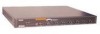
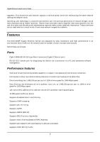
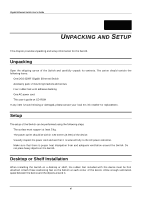
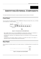
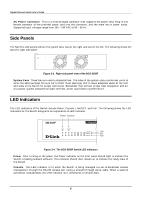
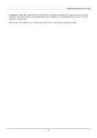
Gigabit Ethernet Switch User's Guide 3 3 IDENTIFYING EXTERNAL COMPONENTS This chapter describes the front panel, rear panel, side panels, and LED indicators of the Switch Front Panel The front panel of the Switch consists of eight 1000BASE-SX (SC-type) multimode fiber ports, an RS-232 communication port, and LED indicators. Figure 3-1. Front panel view of the DGS-3208F Switch ♦ Eight Gigabit Ethernet ports of fixed 1000BASE-SX multimode fiber interface for connections to workstations, servers, and networking devices through multimode optical fiber cabling. ♦ An RS-232 DCE console port is for diagnosing the Switch via a connection to a PC and local console management. ♦ Comprehensive LED indicators display the condition of the Switch and status of the network. A description of these LED indicators follows (see LED Indicators). Rear Panel The rear panel of the Switch consists of an AC power connector. The following shows the rear panel of the Switch. Figure 3-2. Rear panel view of the DGS-3208F 7
-
 1
1 -
2
-
3
-
4
-
5
-
6
-
7
-
8
-
 9
9 -
 10
10 -
 11
11 -
 12
12 -
 13
13 -
 14
14 -
 15
15 -
 16
16 -
 17
17 -
 18
18 -
 19
19 -
20
-
21
-
22
-
23
-
24
-
25
-
26
-
27
-
28
-
29
-
30
-
31
-
32
-
33
-
34
-
35
-
36
-
37
-
38
-
39
-
40
-
41
-
42
-
43
-
44
-
45
-
46
-
47
-
48
-
49
-
50
-
51
-
52
-
53
-
54
-
55
-
56
-
57
-
58
-
59
-
60
-
61
-
62
-
63
-
64
-
65
-
66
-
67
-
68
-
69
-
70
-
71
-
72
-
73
-
74
-
75
-
76
-
77
-
78
-
79
-
80
-
81
-
82
-
83
-
84
-
85
-
86
-
87
-
88
-
89
-
90
-
91
-
92
-
93
-
94
-
95
-
96
-
97
-
98
-
99
-
100
-
101
-
102
-
103
-
104
-
105
-
106
-
107
-
108
-
109
-
110
-
111
-
112
-
113
-
114
-
115
-
116
-
117
-
118
-
119
-
120
-
121
-
122
-
123
-
124
-
125
-
126
-
127
-
128
-
129
-
130
-
131
-
132
-
133
 |
 |