D-Link DGS-3208F Product Manual - Page 15
Side Panels, LED Indicators, Right side panel view of the DGS-3208F
 |
UPC - 790069222092
View all D-Link DGS-3208F manuals
Add to My Manuals
Save this manual to your list of manuals |
Page 15 highlights
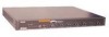
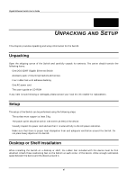
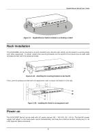
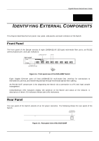
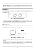
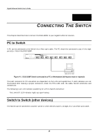
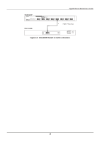
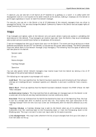
Gigabit Ethernet Switch User's Guide ♦ AC Power Connector This is a three-pronged connector that supports the power cord. Plug in the female connector of the provided power cord into this connector, and the male into a power outlet. Supported input voltages range from 100 ~ 240 VAC at 50 ~ 60 Hz. Side Panels The Switch's side panels contain the system fans, two on the right and one on the left. The following shows the Switch's right side panel. Figure 3-3. Right side panel view of the DGS-3208F ♦ System Fans These fans are used to dissipate heat. The sides of the system also provide heat vents to serve the same purpose. Be sure not to block these openings, and to leave adequate space at the rear and sides of the Switch for proper ventilation. Remember that without proper heat dissipation and air circulation, system components might overheat, which could lead to system failure. LED Indicators The LED indicators of the Switch include Power, Console, Link/ACT, and Full. The following shows the LED indicators for the Switch along with an explanation of each indicator. Figure 3-4. The DGS-3208F Switch LED indicators ♦ Power After turning on the power, the Power indicator on the front panel should light to indicate the Switch is loading onboard software. This indicator should then remain on to indicate the ready state of the Switch. ♦ Console This LED indicator is lit when the Switch is being managed via out-of-band/local console management through the RS-232 console port using a straight-through serial cable. When a secured connection is established, this LED indicator is lit. Otherwise, it remains dark. 8
-
 1
1 -
2
-
3
-
4
-
5
-
6
-
7
-
8
-
9
-
 10
10 -
 11
11 -
 12
12 -
 13
13 -
 14
14 -
 15
15 -
 16
16 -
 17
17 -
 18
18 -
 19
19 -
 20
20 -
21
-
22
-
23
-
24
-
25
-
26
-
27
-
28
-
29
-
30
-
31
-
32
-
33
-
34
-
35
-
36
-
37
-
38
-
39
-
40
-
41
-
42
-
43
-
44
-
45
-
46
-
47
-
48
-
49
-
50
-
51
-
52
-
53
-
54
-
55
-
56
-
57
-
58
-
59
-
60
-
61
-
62
-
63
-
64
-
65
-
66
-
67
-
68
-
69
-
70
-
71
-
72
-
73
-
74
-
75
-
76
-
77
-
78
-
79
-
80
-
81
-
82
-
83
-
84
-
85
-
86
-
87
-
88
-
89
-
90
-
91
-
92
-
93
-
94
-
95
-
96
-
97
-
98
-
99
-
100
-
101
-
102
-
103
-
104
-
105
-
106
-
107
-
108
-
109
-
110
-
111
-
112
-
113
-
114
-
115
-
116
-
117
-
118
-
119
-
120
-
121
-
122
-
123
-
124
-
125
-
126
-
127
-
128
-
129
-
130
-
131
-
132
-
133
 |
 |