D-Link DXS-5000-54S Quick Install Guide - Page 10
LED Indicators, 10G SFP+ Ports, Console Port, USB 2.0 Type A Port, Management Port
 |
View all D-Link DXS-5000-54S manuals
Add to My Manuals
Save this manual to your list of manuals |
Page 10 highlights
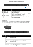
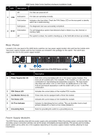
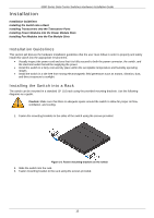
5000 Series Data Center Switches Hardware Installation Guide # Port 1 10G SFP+ Ports 2 40G QSFP+ Ports 3 Console Port 4 USB 2.0 Type A Port 5 Management Port Figure 1-4 Front panel view of the DXS-5000-54S Description 48 10G fiber optic access ports. 6 40G fiber optic access ports. Mini-USB console port for accessing the command line interface (CLI) of this switch for configuration, management, and monitoring. USB 2.0 port for connecting a USB storage device. RJ-45 port for out-of band-management to configure the switch without being connected to the network. LED Indicators Located on the front panel of all the 5000 Series switches are the following LED indicators: PSU1, PSU2, FAN, and STAT. To the left of the LED panel is the reset button used to reset the switch back to factory default settings. Figure 1-5 LED indicators for the 5000 Series switches # LED Description Off 1 PSU1 Solid green Solid amber Off 2 PSU2 Solid green Solid amber The switch is turned off. The switch is powered on and functioning normally. The switch's power supply has failed or is not working properly. The switch is turned off. The switch is powered on and functioning normally. The switch's power supply has failed or is not working properly. 10
-
 1
1 -
2
-
3
-
4
-
 5
5 -
 6
6 -
 7
7 -
 8
8 -
 9
9 -
 10
10 -
 11
11 -
 12
12 -
 13
13 -
 14
14 -
 15
15 -
16
-
17
-
18
-
19
-
20
-
21
-
22
-
23
-
24
-
25
-
26
-
27
-
28
-
29
-
30
-
31
-
32
-
33
-
34
-
35
-
36
-
37
-
38
-
39
-
40
-
41
-
42
-
43
-
44
-
45
-
46
-
47
-
48
-
49
-
50
-
51
-
52
-
53
-
54
-
55
 |
 |
