D-Link DXS-5000-54S Quick Install Guide - Page 11
Rear Panel, Power Supply Modules
 |
View all D-Link DXS-5000-54S manuals
Add to My Manuals
Save this manual to your list of manuals |
Page 11 highlights
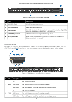
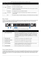
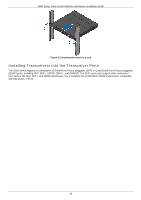
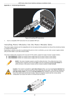
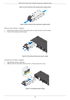
5000 Series Data Center Switches Hardware Installation Guide # LED Description Off The fans are powered off. 3 FAN Solid green Solid amber The fans are operating normally. Indicates a fan has failed. Check the FAN Status LED on the rear panel to identify which fan is malfunctioning. Solid green The diagnostic test was successfully completed. 4 STAT Solid amber The self-diagnostics system has detected a fault or failure (e.g. fan, thermal, or interface fault). Off The system is down, the switch is booting up, or the NOS did not boot up normally. Rear Panel Located on the rear panel of the 5000 Series switches are two power supply module slots and four fan module slots. Two power supply modules and four fan modules are included in the package for this switch. This switch also supports the use of a DC power supply module. Figure 1-6 Rear panel view of the 5000 Series switches # Item 1 Power Supply Slot 1/2 2 PSU Status LED 3 Fan Module Slots (x 4) 4 Fan Status LED 5 Air Flow Indicator 6 Grounding Node Description Both slots come preinstalled with AC or DC power supply modules. The slots can be outfitted with 2 DC modules, 2 AC modules, or 1 DC and 1 AC combination for load sharing and redundancy purposes. The base model only ships with either 2 AC or 2 DC PSUs. An additional AC or DC PSU must be purchased separately to outfit the switch with a 1 AC + 1 DC PSU combination. Indicates the current status of the installed PSU module. These slots can be equipped with a Smart fan module. Indicates the current status of the installed fan module. Indicator for identifying the fan's airflow. This can be either front-to-back exhaust (labeled E) or back-to-front intake (labeled I). Node for grounding the switch to a grounding source. Power Supply Modules The 5000 Series switches ship with two power supply units preinstalled. When the primary power connection fails, the secondary power connection will take over all the power immediately and automatically. The primary and secondary power supply can be either AC or DC supplied, depending on the power supply module inserted, allowing for dual redundancy. 11
-
 1
1 -
2
-
3
-
4
-
5
-
 6
6 -
 7
7 -
 8
8 -
 9
9 -
 10
10 -
 11
11 -
 12
12 -
 13
13 -
 14
14 -
 15
15 -
 16
16 -
17
-
18
-
19
-
20
-
21
-
22
-
23
-
24
-
25
-
26
-
27
-
28
-
29
-
30
-
31
-
32
-
33
-
34
-
35
-
36
-
37
-
38
-
39
-
40
-
41
-
42
-
43
-
44
-
45
-
46
-
47
-
48
-
49
-
50
-
51
-
52
-
53
-
54
-
55
 |
 |
