D-Link DXS-5000-54S Quick Install Guide - Page 15
Installing Power Modules into the Power Module Slots, Appendix A - Technical Specifications
 |
View all D-Link DXS-5000-54S manuals
Add to My Manuals
Save this manual to your list of manuals |
Page 15 highlights
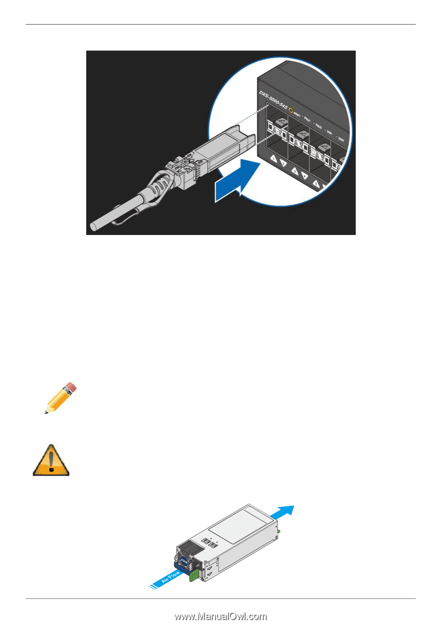
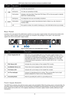
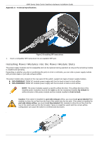
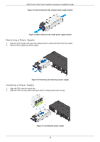
5000 Series Data Center Switches Hardware Installation Guide Appendix A - Technical Specifications. Figure 2-3 Installing SFP transceivers 1. Insert a compatible SFP transceiver into an available SFP port. Installing Power Modules into the Power Module Slots The power supply modules are hot-swappable and can be replaced during operation as long as the remaining module is installed and operating. Depending on whether you plan on positioning the ports in a hot or cold aisle, you can order a power supply module with port-side intake or port-side exhaust airflow. The power module slots, located on the rear panel of this switch, support two types of power supply modules. DXS-PWR550AC: 550W AC modular power supply with front-to-back or back-to-front airflow. DXS-PWR800DC: 800W DC modular power supply with front-to-back or back-to-front airflow. NOTE: The power modules support a specific airflow direction. This airflow direction of the installed power module(s) must be the same as the fan module(s) installed. By default the airflow direction of the power module and fan module installed is front-to-back. Caution: If the switch is installed for port-side exhaust airflow, you must install green-labeled PSU modules to drive the air flow from the front of the switch into the hot aisle. If the switch is installed for port-side intake airflow, you must install blue-labeled PSU modules to drive the air flow from the rear of the switch and out into the hot aisle. Failure to install the switch with the correct airflow configuration can cause the switch to overheat and shut down. . 15
-
 1
1 -
2
-
3
-
4
-
5
-
6
-
7
-
8
-
9
-
 10
10 -
 11
11 -
 12
12 -
 13
13 -
 14
14 -
 15
15 -
 16
16 -
 17
17 -
 18
18 -
 19
19 -
 20
20 -
21
-
22
-
23
-
24
-
25
-
26
-
27
-
28
-
29
-
30
-
31
-
32
-
33
-
34
-
35
-
36
-
37
-
38
-
39
-
40
-
41
-
42
-
43
-
44
-
45
-
46
-
47
-
48
-
49
-
50
-
51
-
52
-
53
-
54
-
55
 |
 |