Dell 2350DN User Guide - Page 7
Understanding the Operator Panel, Two-line LCD display - printer
 |
View all Dell 2350DN manuals
Add to My Manuals
Save this manual to your list of manuals |
Page 7 highlights
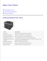
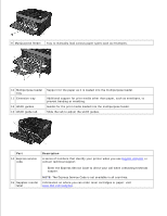
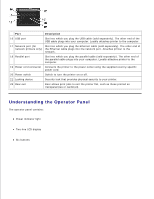
Part Description 16 USB port Slot into which you plug the USB cable (sold separately). The other end of the USB cable plugs into your computer. Locally attaches printer to the computer. 17 Network port (for Slot into which you plug the Ethernet cable (sold separately). The other end of network printers only) the Ethernet cable plugs into the network port. Attaches printer to the network. 18 Parallel port Slot into which you plug the parallel cable (sold separately). The other end of the parallel cable plugs into your computer. Locally attaches printer to the computer. 19 Power cord connector Connects the printer to the power outlet using the supplied country-specific power cord. 20 Power switch Switch to turn the printer on or off. 21 Locking device Security lock that provides physical security to your printer. 22 Rear exit Door allows print jobs to exit the printer flat, such as those printed on transparencies or cardstock. Understanding the Operator Panel The operator panel contains: Power indicator light Two-line LCD display Six buttons
-
 1
1 -
 2
2 -
 3
3 -
 4
4 -
 5
5 -
 6
6 -
 7
7 -
 8
8 -
 9
9 -
 10
10 -
 11
11 -
 12
12 -
13
-
14
-
15
-
16
-
17
-
18
-
19
-
20
-
21
-
22
-
23
-
24
-
25
-
26
-
27
-
28
-
29
-
30
-
31
-
32
-
33
-
34
-
35
-
36
-
37
-
38
-
39
-
40
-
41
-
42
-
43
-
44
-
45
-
46
-
47
-
48
-
49
-
50
-
51
-
52
-
53
-
54
-
55
-
56
-
57
-
58
-
59
-
60
-
61
-
62
-
63
-
64
-
65
-
66
-
67
-
68
-
69
-
70
-
71
-
72
-
73
-
74
-
75
-
76
-
77
-
78
-
79
-
80
-
81
-
82
-
83
-
84
-
85
-
86
-
87
-
88
-
89
-
90
-
91
-
92
-
93
-
94
-
95
-
96
-
97
-
98
-
99
-
100
-
101
-
102
-
103
-
104
-
105
-
106
-
107
-
108
-
109
-
110
-
111
-
112
-
113
-
114
-
115
-
116
-
117
-
118
-
119
-
120
-
121
-
122
-
123
-
124
-
125
-
126
-
127
-
128
-
129
-
130
-
131
-
132
-
133
-
134
-
135
-
136
-
137
-
138
-
139
-
140
-
141
-
142
-
143
-
144
-
145
-
146
-
147
-
148
-
149
-
150
-
151
-
152
-
153
-
154
-
155
-
156
-
157
-
158
-
159
-
160
-
161
-
162
-
163
-
164
-
165
-
166
-
167
-
168
-
169
-
170
-
171
-
172
-
173
-
174
-
175
-
176
-
177
-
178
-
179
-
180
-
181
 |
 |
