Dell Alienware 15 R4 Service Manual - Page 50
Replacing the system board, Procedure
 |
View all Dell Alienware 15 R4 manuals
Add to My Manuals
Save this manual to your list of manuals |
Page 50 highlights
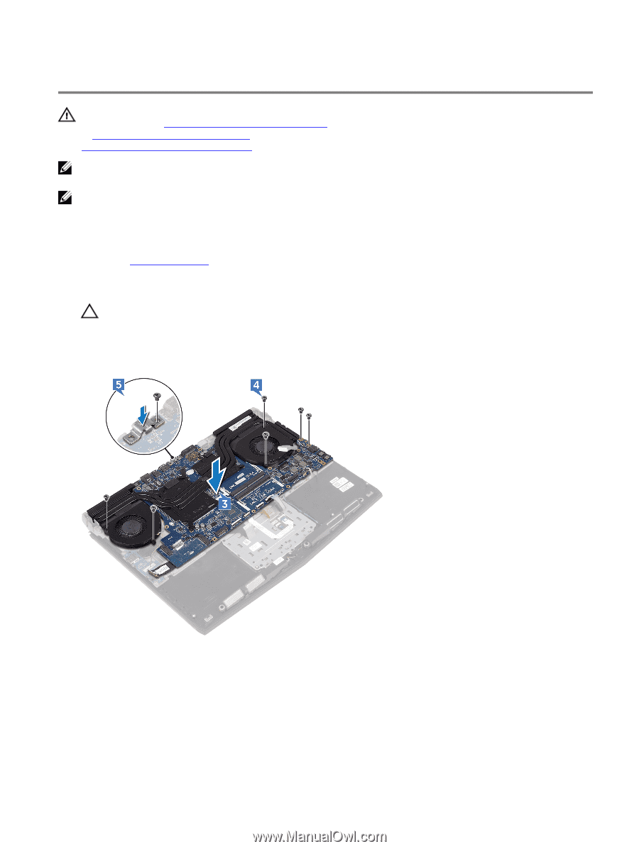
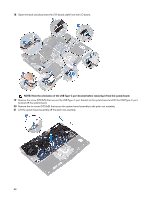
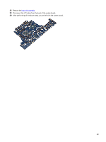
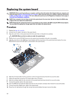
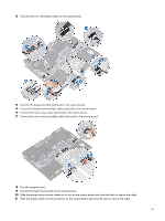
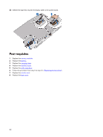
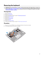
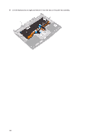
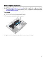
Replacing the system board WARNING: Before working inside your computer, read the safety information that shipped with your computer and follow the steps in Before working inside your computer. After working inside your computer, follow the instructions in After working inside your computer. For more safety best practices, see the Regulatory Compliance home page at www.dell.com/regulatory_compliance. NOTE: Your computer's Service Tag is stored in the system board. You must enter the Service Tag in the BIOS setup program after you replace the system board. NOTE: Replacing the system board removes any changes you have made to the BIOS using the BIOS setup program. You must make the appropriate changes again after you replace the system board. Procedure 1 Replace the heat-sink assembly. 2 Connect the I/O cable to the back of the system board. 3 Align the screw holes on the system board with the screw holes on the palm-rest assembly. CAUTION: Make sure that no cables are under the system board. 4 Replace the six screws (M2.5x5) that secure the system-board assembly to the palm-rest assembly. 5 Align the screw hole on the USB Type-C port bracket with the screw hole on the system board and replace the screw (M2.5x5) that secures the USB Type-C port bracket to the system board. 6 Slide the I/O-board cable into the connector on the I/O-board and close the latch to secure the cable. 7 Adhere the tape that secures the I/O-board cable to the I/O board. 8 Slide the touchpad cable into the connector on the system board and close the latch to secure the cable. 9 Connect the speaker cable to the system board. 10 Insert the RGB per key keyboard cable (optional) into the connector and press down the latch to secure the cable. 11 Connect the power-adapter port cable to the system board. 12 Route the coin-cell battery through the routing channel and adhere the tape to secure the cable. 50
-
 1
1 -
2
-
3
-
4
-
5
-
6
-
7
-
8
-
9
-
10
-
11
-
12
-
13
-
14
-
15
-
16
-
17
-
18
-
19
-
20
-
21
-
22
-
23
-
24
-
25
-
26
-
27
-
28
-
29
-
30
-
31
-
32
-
33
-
34
-
35
-
36
-
37
-
38
-
39
-
40
-
41
-
42
-
43
-
44
-
 45
45 -
 46
46 -
 47
47 -
 48
48 -
 49
49 -
 50
50 -
 51
51 -
 52
52 -
 53
53 -
 54
54 -
 55
55 -
56
-
57
-
58
-
59
-
60
-
61
-
62
-
63
-
64
-
65
-
66
-
67
-
68
-
69
-
70
-
71
-
72
-
73
-
74
-
75
-
76
-
77
-
78
-
79
-
80
-
81
-
82
-
83
-
84
-
85
-
86
-
87
-
88
 |
 |