Dell Alienware 15 R4 Service Manual - Page 71
Replacing the display assembly, Procedure
 |
View all Dell Alienware 15 R4 manuals
Add to My Manuals
Save this manual to your list of manuals |
Page 71 highlights
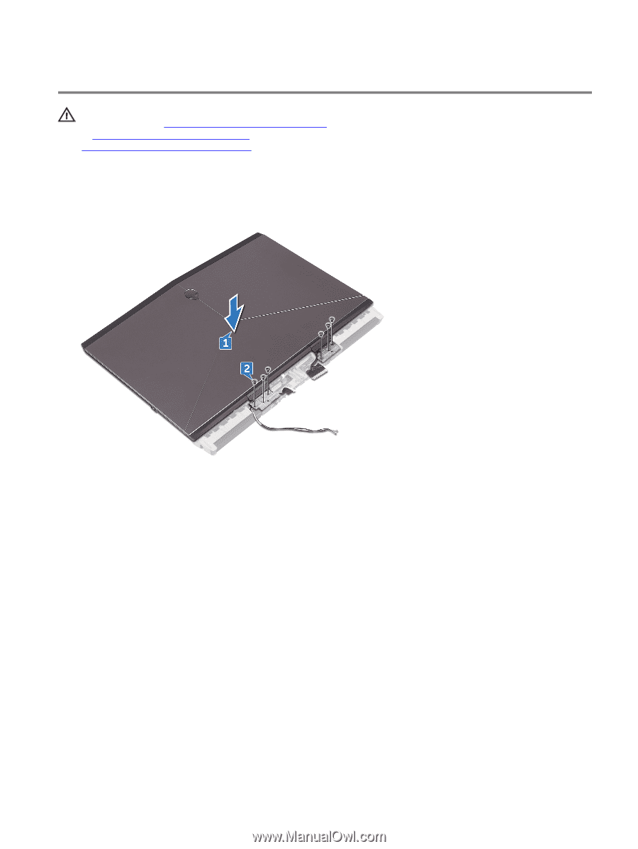
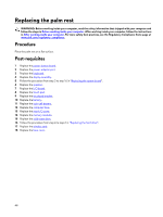
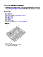
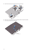
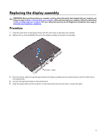
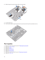
Replacing the display assembly WARNING: Before working inside your computer, read the safety information that shipped with your computer and follow the steps in Before working inside your computer. After working inside your computer, follow the instructions in After working inside your computer. For more safety best practices, see the Regulatory Compliance home page at www.dell.com/regulatory_compliance. Procedure 1 Align the screw holes on the display hinges with the screw holes on the palm-rest assembly. 2 Replace the six screws (M2.5x5) that secure the display assembly to the palm-rest assembly. 3 Push the antenna cables through the gap between the display assembly and the system board to reach the other side of the system board. 4 Connect the logo-board cable to the system board. 5 Slide the display cable into the connector on the system board and close the latch to secure the cable. 71
-
 1
1 -
2
-
3
-
4
-
5
-
6
-
7
-
8
-
9
-
10
-
11
-
12
-
13
-
14
-
15
-
16
-
17
-
18
-
19
-
20
-
21
-
22
-
23
-
24
-
25
-
26
-
27
-
28
-
29
-
30
-
31
-
32
-
33
-
34
-
35
-
36
-
37
-
38
-
39
-
40
-
41
-
42
-
43
-
44
-
45
-
46
-
47
-
48
-
49
-
50
-
51
-
52
-
53
-
54
-
55
-
56
-
57
-
58
-
59
-
60
-
61
-
62
-
63
-
64
-
65
-
 66
66 -
 67
67 -
 68
68 -
 69
69 -
 70
70 -
 71
71 -
 72
72 -
 73
73 -
 74
74 -
 75
75 -
 76
76 -
77
-
78
-
79
-
80
-
81
-
82
-
83
-
84
-
85
-
86
-
87
-
88
 |
 |