Dell Alienware 15 R4 Service Manual - Page 86
Wi-Fi power cycle, System board: BIOS or ROM Read-Only Memory failure
 |
View all Dell Alienware 15 R4 manuals
Add to My Manuals
Save this manual to your list of manuals |
Page 86 highlights
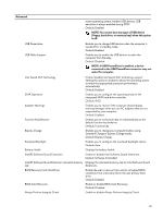
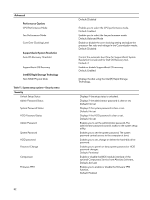
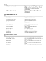
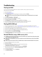
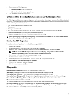
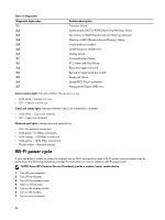
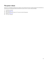
Table 14. Diagnostics Diagnostic light codes 2,1 2,2 2,3 2,4 2,5 2,6 2,7 3,1 3,2 3,3 3,4 3,5 3,6 3,7 Problem description Processor failure System board: BIOS or ROM (Read-Only Memory) failure No memory or RAM (Random-Access Memory) detected Memory or RAM (Random-Access Memory) failure Invalid memory installed System-board or chipset error Display failure Coin-cell battery failure PCI, video card/chip failure Recovery image not found Recovery image found but invalid Power-rail failure System BIOS Flash incomplete Management Engine (ME) error Camera status light: Indicates whether the camera is in use. • Solid white - Camera is in use. • Off - Camera is not in use. Caps Lock status light: Indicates whether Caps Lock is enabled or disabled. • Solid white - Caps Lock enabled. • Off - Caps Lock disabled. Network port light: Indicates network connectivity. • Off - No network connection. • Solid green - 10 Mbps connection. • Solid orange - 100 Mbps connection. • Solid yellow - 1000 Mbps connection. • Flicker yellow - Network activity. Wi-Fi power cycle If your computer is unable to access the Internet due to Wi-Fi connectivity issues a Wi-Fi power cycle procedure may be performed. The following procedure provides the instructions on how to conduct a Wi-Fi power cycle: NOTE: Some ISPs (Internet Service Providers) provide a modem/router combo device. 1 Turn off your computer. 2 Turn off the modem. 3 Turn off the wireless router. 4 Wait for 30 seconds. 5 Turn on the wireless router. 6 Turn on the modem. 7 Turn on your computer. 86
-
 1
1 -
2
-
3
-
4
-
5
-
6
-
7
-
8
-
9
-
10
-
11
-
12
-
13
-
14
-
15
-
16
-
17
-
18
-
19
-
20
-
21
-
22
-
23
-
24
-
25
-
26
-
27
-
28
-
29
-
30
-
31
-
32
-
33
-
34
-
35
-
36
-
37
-
38
-
39
-
40
-
41
-
42
-
43
-
44
-
45
-
46
-
47
-
48
-
49
-
50
-
51
-
52
-
53
-
54
-
55
-
56
-
57
-
58
-
59
-
60
-
61
-
62
-
63
-
64
-
65
-
66
-
67
-
68
-
69
-
70
-
71
-
72
-
73
-
74
-
75
-
76
-
77
-
78
-
79
-
80
-
 81
81 -
 82
82 -
 83
83 -
 84
84 -
 85
85 -
 86
86 -
 87
87 -
 88
88
 |
 |
