Dell Force10 S4820T Installing the S4820T System
Dell Force10 S4820T Manual
 |
View all Dell Force10 S4820T manuals
Add to My Manuals
Save this manual to your list of manuals |
Dell Force10 S4820T manual content summary:
- Dell Force10 S4820T | Installing the S4820T System - Page 1
Installing the S4820T System Publication Date: January 2013 - Dell Force10 S4820T | Installing the S4820T System - Page 2
loss of data and tells you how to avoid the problem. WARNING: A WARNING indicates a potential for property damage, personal injury, or death. Information in this publication is subject to change without notice. © 2013 Dell Force10. All rights reserved. Reproduction of these materials in any manner - Dell Force10 S4820T | Installing the S4820T System - Page 3
the Dell ReadyRails System 24 Two-post Flush-mount Configuration 25 Two-post Center-mount Configuration 26 Four-post Threaded Configuration 27 Installing the S4820T Switch 28 1U Front-rack Installation 28 Attaching the Ground Cable 28 Installing an AC or DC Power Supply 29 Installing - Dell Force10 S4820T | Installing the S4820T System - Page 4
an AC or DC Power Supply 40 Connecting a DC Power Supply to the Power Source 41 Removing Power Connector from an S4820T DC Power Supply 42 6 Fans Components 43 Install a Fan Module 44 Replace a Fan Module 44 7 Management Ports Accessing the RJ-45 Console Port (RS-232 45 Default Configuration - Dell Force10 S4820T | Installing the S4820T System - Page 5
51 Safety Standards and Compliance Agency Certifications 51 Electromagnetic Compatibility (EMC 52 Product Recycling and Disposal 52 9 Technical Support The iSupport Website 55 Accessing iSupport Services 55 Contacting the Technical Assistance Center 56 Requesting a Hardware Replacement 57 |5 - Dell Force10 S4820T | Installing the S4820T System - Page 6
www.dell.com | support.dell.com 6| - Dell Force10 S4820T | Installing the S4820T System - Page 7
and power-up of the S4820T, for software configuration information, refer to the FTOS Configuration Guide for the S4820T System and for Command Line Interface (CLI) information, refer to the FTOS Command Line Reference Guide for the S4820T System. NOTE: User port stacking requires Dell Force10 - Dell Force10 S4820T | Installing the S4820T System - Page 8
www.dell.com | support.dell.com Table 1-1. Information Symbols (continued) Symbol Warning Description S4820T system, refer to the following documents: • FTOS Configuration Guide for the S4820T System • FTOS Command Line Reference Guide for the S4820T System • FTOS Release Notes for the S4820T - Dell Force10 S4820T | Installing the S4820T System - Page 9
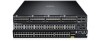
to the 40Gbps switching fabric in the core. The S4820T has 48 ports of RJ-45 10GBase-T and four ports of 40Gbps with features and functions similar to the S4810 product. The S4820T Power Supply Unit (PSU) side (Figure 2-1) contains the PSU, fan modules, and management ports. The S4820T Input/Output - Dell Force10 S4820T | Installing the S4820T System - Page 10
redundant power supply • Current monitoring for Power management • Removable fan that you can manage • Standard 1U chassis high Physical Dimensions The S4820T has the following physical dimensions: • 434 x 460 x 43.5 mm (W x D x H). • 17.09 x 18.11 x 1.71 inches (W x D x H). 10 | The S4820T Switch - Dell Force10 S4820T | Installing the S4820T System - Page 11
through the Command Line Interface (CLI) show commands and with Simple Network Management Protocol (SNMP) traps. For more information about these options, refer to the FTOS Command Line Reference Guide for the S4820T System and the FTOS Configuration Guide for the S4820T System. LED Displays As - Dell Force10 S4820T | Installing the S4820T System - Page 12
dell.com | support.dell.com Table 2-1. System LED Displays Feature Detailed Description System LED • Solid blue - Normal Operation • Blinking blue - Booting • Solid red - Critical system error • Blinking red - Non-critical system error (fan fail, power supply 10GBT Ethernet Port LEDs Feature - Dell Force10 S4820T | Installing the S4820T System - Page 13
Table 2-4. Out of Band Ethernet Port LEDs Feature Detailed Description Link LED • Off - No Link • Solid green - Link on 1Gbps speed • Solid Amber - Link on 100M or 10M speeds Activity LED • Off - No Link • Blinking green - Transmit/Receive is active The S4820T Switch | 13 - Dell Force10 S4820T | Installing the S4820T System - Page 14
list of components required for a successful installation of the S4820T: • S4820T chassis (or multiple chassis, if stacking) • If you ordered AC units, cables to connect the AC power source to each of the chassis' AC power supplies (country/regional configured) • If you ordered DC units, cables to - Dell Force10 S4820T | Installing the S4820T System - Page 15
2-5. Supported Hardware Components Hardware S4820T AC Normal Airflow: 48 port 10G RJ-45 ports with 4 QSFP+ 40G ports, 1 AC power supply and 2 fan subsystems (airflow from I/O side to power supply side) S4820T AC Reverse Airflow: 48 port 10G RJ-45 ports with 4 QSFP+ 40G ports, 1 AC power supply and - Dell Force10 S4820T | Installing the S4820T System - Page 16
16 | The S4820T Switch www.dell.com | support.dell.com - Dell Force10 S4820T | Installing the S4820T System - Page 17
The S4820T is suitable for installation as part of a Common Bond Network (CBN). It can be installed in: • Network telecommunication S4820T should be installed: • Site Selection • Cabinet Placement • Rack Mounting • Grounding • Fans and Airflow • Power • Storing Components NOTE: Install the S4820T - Dell Force10 S4820T | Installing the S4820T System - Page 18
ground point used by the power service in your area. The ground path must be permanent. Grounding Use the S4820T in a Common Bond Network (CBN). You must connect the grounding cables as described in Chapter 4, Installing the S4820T. Fans and Airflow The S4820T fans support two airflow options. Be - Dell Force10 S4820T | Installing the S4820T System - Page 19
the FTOS Command Ling Reference Guide for the S4820T System and FTOS Configuration Guide for the S4820T System. Power Use the appropriate power cord with the S4820T system to connect the chassis to the applicable power source. • If the switch is an AC model, an AC power cord (country/region specific - Dell Force10 S4820T | Installing the S4820T System - Page 20
www.dell.com | support.dell.com • Store on a dry surface or floor, away from direct sunlight, heat, and ESD-preventive wrist or heel ground strap when handling the S4820T and its accessories. After you remove the original packaging, place the S4820T and its components on an antistatic surface. 20 | - Dell Force10 S4820T | Installing the S4820T System - Page 21
a Installing the Dell ReadyRails System b Two-post Flush-mount Configuration c Two-post Center-mount Configuration d Four-post Threaded Configuration 3 Installing the S4820T Switch a 1U Front-rack Installation b Attaching the Ground Cable c Installing an AC or DC Power Supply 4 Installing QSFP - Dell Force10 S4820T | Installing the S4820T System - Page 22
www.dell.com | support.dell.com • At least one PSU • If an AC switch, at least one AC power cord (country/region specific) • If a DC switch, at least one DC power cable • Getting Started Guide • Safety and Regulatory Information • Warranty and Support Information • Software License Agreement - Dell Force10 S4820T | Installing the S4820T System - Page 23
The Dell ReadyRails™ system is provided for one 1U front-rack, and two-post installations. The ReadyRails system includes two separately packaged rail assemblies and two rails that are shipped attached to the sides of the switch. WARNING: This is a condensed reference. Read the safety instructions - Dell Force10 S4820T | Installing the S4820T System - Page 24
www.dell.com | support.dell.com Installing the Dell ReadyRails System The ReadyRails rack mounting system is provided to easily configure your rack for installation of your S4820T switch. The ReadyRails system can be installed using the 1U tool-less method or one of three possible 1U tooled methods - Dell Force10 S4820T | Installing the S4820T System - Page 25
ear (on the switch side of the rail) and remove each casting. Retain the castings for future rack requirements. It is not necessary to remove the rear flange castings. Figure 4-2. Two-post Flush-mount Configuration 2 Attach one rail to the front post flange with two user-supplied screws. Refer to - Dell Force10 S4820T | Installing the S4820T System - Page 26
www.dell.com | support.dell.com Two-post Center-mount Configuration 1 Slide the plunger bracket rearward until it clicks into place and secure the bracket to the front post flange with two user-supplied screws. Refer to Figure 4-3, step 1. Figure 4-3. Two-post Center-mount Configuration 2 Slide the - Dell Force10 S4820T | Installing the S4820T System - Page 27
Figure 4-4, step 1. Retain the castings for future rack requirements. 2 For each rail, attach the front and rear flanges to the post flanges with two user-supplied screws at each end. Refer to Figure 4-4, step 2. Figure 4-4. Four-post Threaded Configuration Installing the S4820T | 27 - Dell Force10 S4820T | Installing the S4820T System - Page 28
the switch from inadvertently sliding out of the rack and falling. Attaching the Ground Cable Use a single M4x0.7 screw to attach the ground cable to the chassis. The cable itself is not included with the S4820T. To properly ground the chassis, Dell Force10 recommends using a 6AWG one-hole lug, #10 - Dell Force10 S4820T | Installing the S4820T System - Page 29
The S4820T supports AC and DC power supplies with two air-flow directions (I/O to PSU or PSU to I/O). Two PSUs are required for full redundancy, but the system will operate with a single PSU. NOTE: If you use a single PSU, you must install a blank plate in the other PSU slot. Dell Force10 recommends - Dell Force10 S4820T | Installing the S4820T System - Page 30
the external power source (either AC wall outlet or DC rack bus bar). 5 If you have a redundant PSU (2nd PSU), repeat steps 1 through 5 above using the 2nd PSU slot on the S4820T switch. NOTE: The system powers up as soon as the cables are connected between the power supply and the power source. 30 - Dell Force10 S4820T | Installing the S4820T System - Page 31
tug repeatedly on the tab. Splitting QSFP+ Ports to SFP+ or RJ-45 Ports The S4820T supports splitting a single 40G QSFP+ port into four 10G SFP+ ports or four 10G RJ-45 ports using one of the supported breakout cables. For the system to recognize the port type change, you must enter the stack-unit - Dell Force10 S4820T | Installing the S4820T System - Page 32
www.dell.com | support.dell.com Powering Up the S4820T Switch Supply power to the S4820T after it is mounted in a rack or cabinet. Dell Force10 recommends re-inspecting your system prior to powering up. Verify that: • Equipment is properly secured to the rack and properly grounded. • Equipment rack - Dell Force10 S4820T | Installing the S4820T System - Page 33
0 Stack Group 2 Stack Group 10 SG-12 SG-14 You can connect the systems while they are powered down or up. Stacking ports are bi-directional. The S4820T supports stacking in either a ring or a cascade topology (Figure 4-8). To provide redundant connectivity, Dell Force10 recommends using the ring - Dell Force10 S4820T | Installing the S4820T System - Page 34
any of the RJ-45 or QSFP+ ports for stacking, provided it is configured as a stacking port. CAUTION: To connect S4820T systems, use only Dell Force10 supported stacking cables. To connect two S4820T systems in a ring (Figure 4-9), starting with the S4820T at the bottom of the stack, follow these - Dell Force10 S4820T | Installing the S4820T System - Page 35
cable between the two units, in a second stacking port, as shown in Figure 4-10. CAUTION: To connect S4820T systems, use only Dell Force10 supported stacking cables. To connect three S4820T systems in a ring (Figure 4-10), starting with the S4820T at the bottom of the stack, follow these steps - Dell Force10 S4820T | Installing the S4820T System - Page 36
on the order in which they come on-line. So, when setting up a new set of switches in a stack, you should have no trouble forcing the identification of the management unit and unit IDs by methodically supplying power to the units in your preferred sequence. Similarly, when you add a new unit to the - Dell Force10 S4820T | Installing the S4820T System - Page 37
For more information about removing a unit from a stack and other stacking commands, refer to the Stacking chapter in the FTOS Configuration Guide for the S4820T System and the Stacking Commands chapter in the FTOS Command Line Reference Guide for the S4820T System. Installing the S4820T | 37 - Dell Force10 S4820T | Installing the S4820T System - Page 38
38 | Installing the S4820T www.dell.com | support.dell.com - Dell Force10 S4820T | Installing the S4820T System - Page 39
The S4820T supports AC power supplies with two air-flow directions (normal and reversed). Two PSUs are required for full redundancy, but the system will operate with a single PSU. NOTE: If you use a single PSU, you must install a blank plate in the other PSU slot. Dell Force10 recommends using power - Dell Force10 S4820T | Installing the S4820T System - Page 40
Interfacing with AC Power Ports, use an external SPD at the AC input of the router. Installing an AC or DC Power Supply To install an AC or DC power supply, follow these steps: NOTE: The PSU slides into the slot smoothly. Do not force a PSU into a slot as this may damage the PSU or the S4820T - Dell Force10 S4820T | Installing the S4820T System - Page 41
up as soon as the cables are connected between the power supply and the power source. Connecting a DC Power Supply to the Power Source Each DC powered S4820T comes with a set containing a pre-wired (3-inch 8AWG) power supply connector and a four-screw wiring block. One set is provided for each - Dell Force10 S4820T | Installing the S4820T System - Page 42
and right levered clamps lock into place. WARNING: Never try to force the power connector into or out of the DC PSU power socket. Removing Power Connector from an S4820T DC Power Supply To remove the power connector from an S4820T DC PSU, squeeze together the levers on both sides of the connector - Dell Force10 S4820T | Installing the S4820T System - Page 43
S4820T comes from the factory with one power supply unit (PSU) and two fan modules installed in the chassis (see Figure 6-1). The fan modules and the integrated fan-power supply integrated fan/power supply modules, you can order and install fan modules separately. The S4820T supports two airflow - Dell Force10 S4820T | Installing the S4820T System - Page 44
dell.com | support.dell.com Install a Fan Module CAUTION: DO NOT mix airflow directions. Both fans must use the same airflow direction (reverse or normal). If the airflows are mismatched, an error message appears and the system shuts down. 00:02:19:%S4820T minute or the system powers down. Use the - Dell Force10 S4820T | Installing the S4820T System - Page 45
7 Management Ports Besides the 10 Gigabit and 40 Gigabit switch ports, the S4820T provides several ports for management and storage. Accessing the RJ-45 Console Port (RS-232) NOTE: Before starting this procedure, be sure that your PC has a 9-pin serial port and that you have a terminal emulation - Dell Force10 S4820T | Installing the S4820T System - Page 46
.com | support.dell.com Default Configuration A version of FTOS is pre-loaded onto the S4820T switch; however, the switch is not configured when you power it up for the first time (except for the default host name, which is FTOS). You must configure the switch using the CLI. 46 | Management Ports - Dell Force10 S4820T | Installing the S4820T System - Page 47
sections: • Chassis Physical Design • Environmental Parameters • Power Requirements • IEEE Standards • Agency Compliance Caution: equivalent type. Dispose of the batteries according to the manufacturer's instructions. Chassis Physical Design Parameter Height Width Depth Weight Specifications 1.71 - Dell Force10 S4820T | Installing the S4820T System - Page 48
www.dell.com | support.dell.com Power Requirements The tables below represents the PSU's capabilities and does not represent the S4820T's operation. AC Input Specification Parameter Power supply Maximum current draw per system Maximum power consumption Maximum power consumption Typical power - Dell Force10 S4820T | Installing the S4820T System - Page 49
) • Force10 (PVST+) • MTU (12,000 bytes) Agency Compliance Network Equipment Building Systems (NEBS) Compliance • Use shielded cables for ports 0 - 48. You must ground the shields at both ends. • Use only reverse airflow configurations in a NEBS-compliant installation. • Fit the power supplies and - Dell Force10 S4820T | Installing the S4820T System - Page 50
Member States relating to electromagnetic compatibility. Force 10 Networks can not accept responsibility for any failure to satisfy the protection requirements resulting from a non-recommended modification of this product, including the fitting of non-Dell Force10 option cards. This product has been - Dell Force10 S4820T | Installing the S4820T System - Page 51
used in a domestic environment, radio disturbance may arise. When such trouble occurs, the user may be required to take corrective actions. WARNING: Use the AC power cords with Dell Force10 equipment only. Do not use Dell Force10 AC power cords with any unauthorized hardware. Korean Certification of - Dell Force10 S4820T | Installing the S4820T System - Page 52
| support.dell.com • EN 60950-1, 2nd Edition • EN 60825-1, 1st Edition • EN 60825-1 Safety of Laser Products-Part 1: Equipment Classification Requirements and User's Guide • EN 60825-2 Safety of Laser Products-Part 2: Safety of Optical Fibre Communication Systems • FDA Regulation 21CFR 1040.10 and - Dell Force10 S4820T | Installing the S4820T System - Page 53
IT and Telecommunications Products Dell Force10 switches are labeled in accordance Dell Force10 product recycling offerings, see the WEEE Recycling instructions on iSupport at: https://www.force10networks.com/CSPortal20/Support/WEEEandRecycling.pdf. For more information, contact the Dell Force10 - Dell Force10 S4820T | Installing the S4820T System - Page 54
54 | Specifications www.dell.com | support.dell.com - Dell Force10 S4820T | Installing the S4820T System - Page 55
upgrades and patches, and open and manage your Technical Assistance Center (TAC) cases. Dell Force10 iSupport provides integrated, secure access to these services. Accessing iSupport Services The URL for iSupport is http://www.force10networks.com/support/. You must have a userid and password - Dell Force10 S4820T | Installing the S4820T System - Page 56
Center How to Contact Dell Force10 TAC Information to Submit When Opening a Support Case Managing Your Case Downloading Software Updates Technical Documentation Contact Information Log in to iSupport at http://www.force10networks.com/support/ and select the Service Request tab. • Your name - Dell Force10 S4820T | Installing the S4820T System - Page 57
support case. Open a support case by: • Using the Create Service Request form on the iSupport page (see Contacting the Technical Assistance Center). • Contacting Dell Force10 -support [non-paged] command.) - Console captures showing the error messages - Console captures showing the troubleshooting - Dell Force10 S4820T | Installing the S4820T System - Page 58
58 | Technical Support www.dell.com | support.dell.com - Dell Force10 S4820T | Installing the S4820T System - Page 59
- Dell Force10 S4820T | Installing the S4820T System - Page 60
Printed in the U.S.A. www.dell.com | support.dell.com
-
 1
1 -
 2
2 -
 3
3 -
 4
4 -
 5
5 -
 6
6 -
 7
7 -
8
-
9
-
10
-
11
-
12
-
13
-
14
-
15
-
16
-
17
-
18
-
19
-
20
-
21
-
22
-
23
-
24
-
25
-
26
-
27
-
28
-
29
-
30
-
31
-
32
-
33
-
34
-
35
-
36
-
37
-
38
-
39
-
40
-
41
-
42
-
43
-
44
-
45
-
46
-
47
-
48
-
49
-
50
-
51
-
52
-
53
-
54
-
55
-
56
-
57
-
58
-
59
-
60
 |
 |

Installing the S4820T System
Publication Date: January 2013