Dell Force10 S4820T Installing the S4820T System - Page 11
Chassis Ports, Determining System Status, LED Displays - management port
 |
View all Dell Force10 S4820T manuals
Add to My Manuals
Save this manual to your list of manuals |
Page 11 highlights
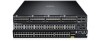
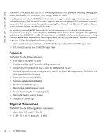
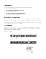
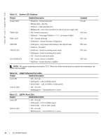
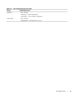
Chassis Ports The following is a list of the standard ports located on each S4820T chassis: • Serial RS-232 port (RJ-45 type) • Out of band Ethernet management port (RJ-45 type) • Forty-eight 1/10Gbps RJ-45 ports • Four 40Gbps QSFP+ ports for four 40Gbps transceivers • One Universal Serial Bus port (USB Type-A) Determining System Status You can view S4820T status information in several ways, including Light Emitting Diodes (LEDs) and boot menu options. Also, you can view status information through the Command Line Interface (CLI) show commands and with Simple Network Management Protocol (SNMP) traps. For more information about these options, refer to the FTOS Command Line Reference Guide for the S4820T System and the FTOS Configuration Guide for the S4820T System. LED Displays As shown in Figure 2-1 and Figure 2-2, the S4820T includes LED displays on the front and back of the chassis. Figure 2-3 enumerates the S4820T chassis LEDs. See Table 2-1 through Table 2-4 provide a detailed description of each LED's meaning. Figure 2-3. Port LEDs 12 5 System LED 3 4 6 7 67 1 - Locator LED (Blue) 2 - Stack LED (Blue/Green) 3 - Temp LED (Red) 4 - Diag LED (Green) 5 - FAN LED (Green/Red) 6 - Link LED (Green/Amber) 7 - Activity LED (Blinking Green) The S4820T Switch | 11
-
 1
1 -
2
-
3
-
4
-
5
-
 6
6 -
 7
7 -
 8
8 -
 9
9 -
 10
10 -
 11
11 -
 12
12 -
 13
13 -
 14
14 -
 15
15 -
 16
16 -
17
-
18
-
19
-
20
-
21
-
22
-
23
-
24
-
25
-
26
-
27
-
28
-
29
-
30
-
31
-
32
-
33
-
34
-
35
-
36
-
37
-
38
-
39
-
40
-
41
-
42
-
43
-
44
-
45
-
46
-
47
-
48
-
49
-
50
-
51
-
52
-
53
-
54
-
55
-
56
-
57
-
58
-
59
-
60
 |
 |
