Dell Force10 S4820T Installing the S4820T System - Page 12
Table 2-2., 10GBT Ethernet Port LEDs, QSFP+ Port LEDs, System LED Displays, Feature
 |
View all Dell Force10 S4820T manuals
Add to My Manuals
Save this manual to your list of manuals |
Page 12 highlights
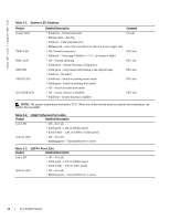
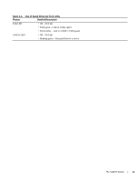
www.dell.com | support.dell.com Table 2-1. System LED Displays Feature Detailed Description System LED • Solid blue - Normal Operation • Blinking blue - Booting • Solid red - Critical system error • Blinking red - Non-critical system error (fan fail, power supply fail) TEMP LED • Off: Normal temperature • Solid red - "Over-temp" (Refer to NOTE: at bottom of table) DIAG LED • Off - Normal operating • Solid green - System Booting or Diagnostics FAN LED • Solid green - fan powered and running at the expected rpm • Solid red - fan failed STACK LED • Solid blue - Switch in stacking master mode • Solid green- Switch in stacking slave mode • Off - Switch in stand alone mode LOCATOR LED • Off - locator function is disabled • Solid blue - locator function is enabled Comment I/O side PSU side PSU side PSU side PSU side PSU side NOTE: The system temperature threshold is 75°C. When one of the thermal sensors exceeds this temperature, the TEMP LED turns RED. Table 2-2. 10GBT Ethernet Port LEDs Feature Detailed Description Link LED • Off - No Link • Solid green - Link on 10Gbps speed • Solid Amber - Link on 100M or 1Gbps speeds Activity LED • Off - No Link • Blinking green - Transmit/Receive is active Table 2-3. QSFP+ Port LEDs Feature Detailed Description Link LED • Off - No Link • Solid green - Link on 40Gbps speed • Solid Amber - Link on other speeds Activity LED • Off - No Link • Blinking green - Transmit/Receive is active 12 | The S4820T Switch
-
 1
1 -
2
-
3
-
4
-
5
-
6
-
 7
7 -
 8
8 -
 9
9 -
 10
10 -
 11
11 -
 12
12 -
 13
13 -
 14
14 -
 15
15 -
 16
16 -
 17
17 -
18
-
19
-
20
-
21
-
22
-
23
-
24
-
25
-
26
-
27
-
28
-
29
-
30
-
31
-
32
-
33
-
34
-
35
-
36
-
37
-
38
-
39
-
40
-
41
-
42
-
43
-
44
-
45
-
46
-
47
-
48
-
49
-
50
-
51
-
52
-
53
-
54
-
55
-
56
-
57
-
58
-
59
-
60
 |
 |