Dell Inspiron 16 Plus 7640 Owners Manual - Page 76
System board callouts, Speaker cable connector
 |
View all Dell Inspiron 16 Plus 7640 manuals
Add to My Manuals
Save this manual to your list of manuals |
Page 76 highlights
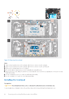
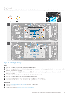
About this task NOTE: If either the system board or the heat sink is replaced, use the thermal grease that is provided in the kit to ensure that thermal conductivity is achieved. The following image indicates the connectors on your system board. Figure 51. System board callouts 1. Fan cable connector 2. Display-assembly cable connector 3. Power-adapter port cable connector 4. I/O board-cable connector 5. M.2 wireless card slot 6. Touchpad-cable connector 7. Keyboard-cable connector 8. Speaker cable connector 9. Keyboard-backlight cable connector 10. Battery cable connector 11. M.2 solid-state drive slot The following image(s) indicate the location of the system board and provides a visual representation of the installation procedure. 76 Removing and installing Field Replaceable Units (FRUs)
-
 1
1 -
2
-
3
-
4
-
5
-
6
-
7
-
8
-
9
-
10
-
11
-
12
-
13
-
14
-
15
-
16
-
17
-
18
-
19
-
20
-
21
-
22
-
23
-
24
-
25
-
26
-
27
-
28
-
29
-
30
-
31
-
32
-
33
-
34
-
35
-
36
-
37
-
38
-
39
-
40
-
41
-
42
-
43
-
44
-
45
-
46
-
47
-
48
-
49
-
50
-
51
-
52
-
53
-
54
-
55
-
56
-
57
-
58
-
59
-
60
-
61
-
62
-
63
-
64
-
65
-
66
-
67
-
68
-
69
-
70
-
 71
71 -
 72
72 -
 73
73 -
 74
74 -
 75
75 -
 76
76 -
 77
77 -
 78
78 -
 79
79 -
 80
80 -
 81
81 -
82
-
83
-
84
-
85
-
86
-
87
-
88
-
89
-
90
-
91
-
92
-
93
-
94
-
95
-
96
-
97
-
98
-
99
-
100
-
101
-
102
-
103
-
104
-
105
-
106
 |
 |
