Dell Inspiron 1720 Service Manual - Page 19
Processor Module
 |
View all Dell Inspiron 1720 manuals
Add to My Manuals
Save this manual to your list of manuals |
Page 19 highlights
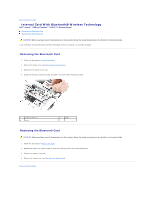
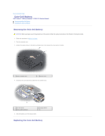
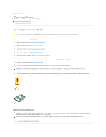
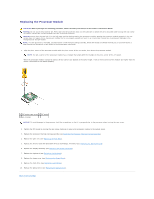
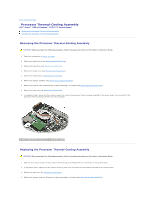
Back to Contents Page Processor Module Dell™ Vostro™ 1700 and Inspiron™ 1720/1721 Service Manual Removing the Processor Module Replacing the Processor Module Removing the Processor Module CAUTION: Before you begin the following procedure, follow the safety instructions in the Product Information Guide. 1. Follow the instructions in Before You Begin. 2. Remove the optical drive (see Removing the Optical Drive). 3. Remove the hard drive (see Removing a Hard Drive). 4. Remove the hinge cover (see Removing the Hinge Cover). 5. Remove the keyboard (see Removing the Keyboard). 6. Remove the display assembly (see Removing the Display Assembly). 7. Remove the internal card with Bluetooth wireless technology, if installed (see Removing the Bluetooth Card). 8. Remove the palm rest (see Removing the Palm Rest). 9. Remove the processor thermal-cooling assembly (see Removing the Processor Thermal-Cooling Assembly). NOTICE: To avoid damage to the processor, hold the screwdriver so that it is perpendicular to the processor when turning the cam screw. 10. To loosen the ZIF socket, use a small, flat-blade screwdriver and rotate the ZIF-socket cam screw counterclockwise until it comes to the cam stop. 1 ZIF-socket cam screw 2 ZIF socket NOTICE: To ensure maximum cooling for the processor, do not touch the heat transfer areas on the processor thermal-cooling assembly. The oils in your skin can reduce the heat transfer capability of the thermal pads. NOTICE: When removing the processor module, pull the module straight up. Be careful not to bend the pins on the processor module. 11. Lift the processor module from the ZIF socket.
-
 1
1 -
2
-
3
-
4
-
5
-
6
-
7
-
8
-
9
-
10
-
11
-
12
-
13
-
 14
14 -
 15
15 -
 16
16 -
 17
17 -
 18
18 -
 19
19 -
 20
20 -
 21
21 -
 22
22 -
 23
23 -
 24
24 -
25
-
26
-
27
-
28
-
29
-
30
-
31
-
32
-
33
-
34
-
35
-
36
-
37
-
38
-
39
-
40
-
41
-
42
-
43
-
44
-
45
-
46
-
47
-
48
-
49
-
50
-
51
-
52
-
53
-
54
-
55
-
56
-
57
-
58
-
59
-
60
-
61
-
62
-
63
-
64
-
65
-
66
-
67
-
68
 |
 |