Dell Inspiron 1720 Service Manual - Page 6
Modem Connector - replacement keyboard
 |
View all Dell Inspiron 1720 manuals
Add to My Manuals
Save this manual to your list of manuals |
Page 6 highlights
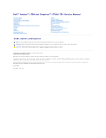
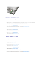
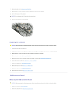
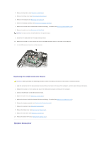
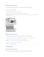
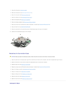
3. Remove the hard drive (see Removing a Hard Drive). 4. Remove the hinge cover (see Removing the Hinge Cover). 5. Remove the keyboard (see Removing the Keyboard). 6. Remove the display assembly (see Removing the Display Assembly). 7. Remove the internal card with Bluetooth wireless technology, if installed (see Removing the Bluetooth Card). 8. Remove the palm rest (see Removing the Palm Rest). NOTICE: Do not disconnect the CIR cable from the system board. 9. Disconnect the USB cable from the USB connector board. 10. Remove the two M2.5 x 5-mm screws that secure the USB connnector board to the base of the computer. 11. Lift the USB connector board out of the computer. Replacing the USB Connector Board CAUTION: Before you begin the following procedure, follow the safety instructions in the Product Information Guide. 1. Align the screw holes in the USB connector board with the screw holes in the base of the computer, and then lower the board into place. 2. Replace the two M2.5 x 5-mm screws and secure the USB connector board to the base of the computer. 3. Connect the USB cable to the USB connector board. 4. Replace the palm rest (see Replacing the Palm Rest). 5. Replace the internal card with Bluetooth wireless technology, if installed (see Replacing the Bluetooth Card). 6. Replace the display assembly (see Replacing the Display Assembly). 7. Replace the keyboard (see Replacing the Keyboard). 8. Replace the hinge cover (see Replacing the Hinge Cover). 9. Replace the hard drive (see Replacing a Hard Drive). 10. Replace the optical drive (see Replacing the Optical Drive). Modem Connector
-
 1
1 -
 2
2 -
 3
3 -
 4
4 -
 5
5 -
 6
6 -
 7
7 -
 8
8 -
 9
9 -
 10
10 -
 11
11 -
 12
12 -
13
-
14
-
15
-
16
-
17
-
18
-
19
-
20
-
21
-
22
-
23
-
24
-
25
-
26
-
27
-
28
-
29
-
30
-
31
-
32
-
33
-
34
-
35
-
36
-
37
-
38
-
39
-
40
-
41
-
42
-
43
-
44
-
45
-
46
-
47
-
48
-
49
-
50
-
51
-
52
-
53
-
54
-
55
-
56
-
57
-
58
-
59
-
60
-
61
-
62
-
63
-
64
-
65
-
66
-
67
-
68
 |
 |