Dell Inspiron 1720 Service Manual - Page 28
Display Latch - inverter
 |
View all Dell Inspiron 1720 manuals
Add to My Manuals
Save this manual to your list of manuals |
Page 28 highlights
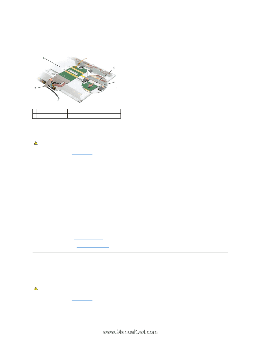
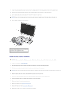
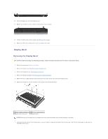
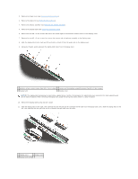
10. Use the pull tab to disconnect the bottom flex-cable connector from the inverter connector. 11. Press inward on the metal clamps on both sides of the top flex-cable connector and gently pull to disconnect the top flex-cable connector from the display locking connector. 1 back of display planel 2 pull tab on bottom flex-cable connector 3 top flex-cable connector 4 metal clamps (2) Replacing the Display Panel CAUTION: Before you begin the following procedure, follow the safety instructions in the Product Information Guide. 1. Follow the instructions in Before You Begin. 2. Connect the top flex-cable connector to the display connector. 3. Connect the bottom flex-cable connector to the inverter connector. 4. Align the screw holes on the display panel with the corresponding screw holes and guide pins on the top cover. 5. With the top of the display panel raised slightly, slide the camera/microphone cable into the camera/microphone connector, then rotate the camera/microphone connector latch downward to secure the cable. 6. Gently lower the display panel into place. 7. Replace the two M2.5 x 5-mm screws at the bottom of the display panel. 8. Replace the eight M2 x 3-mm screws (four on each side of the display panel) to secure the display panel to the display cover. 9. Replace the display bezel (see Replacing the Display Bezel). 10. Replace the display assembly (see Replacing the Display Assembly). 11. Replace the keyboard (see Replacing the Keyboard). 12. Replace the hinge cover (see Replacing the Hinge Cover). Display Latch Removing the Display Latch CAUTION: Before you begin the following procedure, follow the safety instructions in the Product Information Guide. 1. Follow the instructions in Before You Begin.
-
 1
1 -
2
-
3
-
4
-
5
-
6
-
7
-
8
-
9
-
10
-
11
-
12
-
13
-
14
-
15
-
16
-
17
-
18
-
19
-
20
-
21
-
22
-
 23
23 -
 24
24 -
 25
25 -
 26
26 -
 27
27 -
 28
28 -
 29
29 -
 30
30 -
 31
31 -
 32
32 -
 33
33 -
34
-
35
-
36
-
37
-
38
-
39
-
40
-
41
-
42
-
43
-
44
-
45
-
46
-
47
-
48
-
49
-
50
-
51
-
52
-
53
-
54
-
55
-
56
-
57
-
58
-
59
-
60
-
61
-
62
-
63
-
64
-
65
-
66
-
67
-
68
 |
 |