Dell Inspiron 1720 Service Manual - Page 29
Removing the Hinge Cover, Removing the Keyboard, Removing the Display Assembly, Removing the Display
 |
View all Dell Inspiron 1720 manuals
Add to My Manuals
Save this manual to your list of manuals |
Page 29 highlights
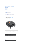
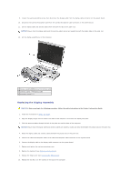
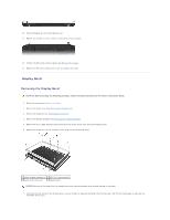
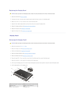
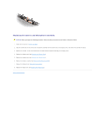
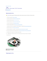
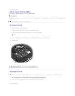
2. Remove the hinge cover (see Removing the Hinge Cover). 3. Remove the keyboard (see Removing the Keyboard). 4. Remove the display assembly (see Removing the Display Assembly). 5. Remove the display bezel (see Removing the Display Bezel). 6. Remove the two M2 x 3-mm screws that secure the inside edges of the wireless antenna covers to the display cover. 7. Remove the two M2 x 3-mm screws that secure the camera and microphone assembly to the display cover. 8. Slide the display latch to the right and lift each side to detach it from the guide slot on the display cover. 9. Using your fingers, gently separate the display latch cover from the display cover. 1 wireless antenna cover screws (two M2 x 3-mm screws) 2 camera and microphone assembly screws (two M2 x 3-mm screws) 3 display latch 4 display cover NOTICE: The display latch spring may be covered by a plastic sleeve. Neither the spring nor the plastic sleeve are secured to the latch assembly and can be easily misplaced. When removing the display latch, place the spring and plastic sleeve in a secure location. 10. Remove the display latch spring and set it aside. 11. Slide the display latch to the right, then carefully flex the left side and lift to detach the left side from the display latch cover. Slide the display latch to the left, then carefully flex the right side and lift to detach the right side from the cover. 1 display cover 2 display latch 3 display latch spring
-
 1
1 -
2
-
3
-
4
-
5
-
6
-
7
-
8
-
9
-
10
-
11
-
12
-
13
-
14
-
15
-
16
-
17
-
18
-
19
-
20
-
21
-
22
-
23
-
 24
24 -
 25
25 -
 26
26 -
 27
27 -
 28
28 -
 29
29 -
 30
30 -
 31
31 -
 32
32 -
 33
33 -
 34
34 -
35
-
36
-
37
-
38
-
39
-
40
-
41
-
42
-
43
-
44
-
45
-
46
-
47
-
48
-
49
-
50
-
51
-
52
-
53
-
54
-
55
-
56
-
57
-
58
-
59
-
60
-
61
-
62
-
63
-
64
-
65
-
66
-
67
-
68
 |
 |