Dell Inspiron 1720 Service Manual - Page 32
Removing the Fan, Replacing the Fan - graphics card
 |
View all Dell Inspiron 1720 manuals
Add to My Manuals
Save this manual to your list of manuals |
Page 32 highlights
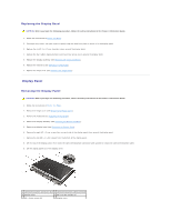
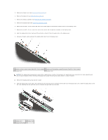
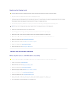
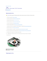
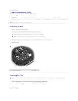
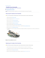
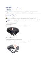
Back to Contents Page Fan Dell™ Vostro™ 1700 and Inspiron™ 1720/1721 Service Manual Removing the Fan Replacing the Fan Removing the Fan CAUTION: Before you begin the following procedure, follow the safety instructions in the Product Information Guide. 1. Follow the instructions in Before You Begin. 2. Remove the optical drive (see Removing the Optical Drive). 3. Remove the hard drive (see Removing a Hard Drive). 4. Remove the hinge cover (see Removing the Hinge Cover). 5. Remove the keyboard (see Removing the Keyboard). 6. Remove the display assembly (see Removing the Display Assembly). 7. Remove the internal card with Bluetooth wireless technology, if installed (see Removing the Bluetooth Card). 8. Remove the palm rest (see Removing the Palm Rest). 9. Remove the graphics card assembly, if installed (see Removing the Graphics Card Assembly). 10. Remove the processor thermal-cooling assembly (see Removing the Processor Thermal-Cooling Assembly). 11. Disconnect the fan connector from the system board connector. 12. In sequential order, remove the four M2.5 x 5-mm screws that secure the fan to the base of the computer. 13. Remove the fan. 1 M2.5 x 5-mm screws (4) 2 fan 3 fan connector Replacing the Fan
-
 1
1 -
2
-
3
-
4
-
5
-
6
-
7
-
8
-
9
-
10
-
11
-
12
-
13
-
14
-
15
-
16
-
17
-
18
-
19
-
20
-
21
-
22
-
23
-
24
-
25
-
26
-
 27
27 -
 28
28 -
 29
29 -
 30
30 -
 31
31 -
 32
32 -
 33
33 -
 34
34 -
 35
35 -
 36
36 -
 37
37 -
38
-
39
-
40
-
41
-
42
-
43
-
44
-
45
-
46
-
47
-
48
-
49
-
50
-
51
-
52
-
53
-
54
-
55
-
56
-
57
-
58
-
59
-
60
-
61
-
62
-
63
-
64
-
65
-
66
-
67
-
68
 |
 |