Dell Inspiron 1720 Service Manual - Page 24
Display
 |
View all Dell Inspiron 1720 manuals
Add to My Manuals
Save this manual to your list of manuals |
Page 24 highlights
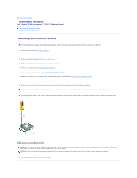
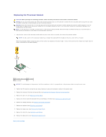
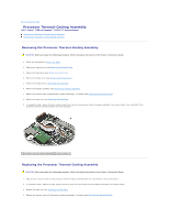
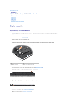
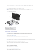
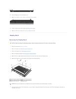
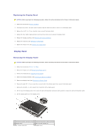
Back to Contents Page Display Dell™ Vostro™ 1700 and Inspiron™ 1720/1721 Service Manual Display Assembly Display Bezel Display Panel Display Latch Camera and Microphone Assembly Display Assembly Removing the Display Assembly CAUTION: Before you begin the following procedure, follow the safety instructions in the Product Information Guide. 1. Follow the instructions in Before You Begin. 2. Close the display and turn the computer over. 3. Loosen the captive screws that secure the Mini Card compartment cover, then remove the cover and set it aside. 1 captive screws (2) 2 Mini Card compartment cover 4. Disconnect antenna cables from any installed Mini Cards (see Wireless Mini Cards). 5. Remove the two M2.5 x 8-mm screws from the bottom of the computer. 6. Remove the two M2.5 x 8-mm screws from the back of the computer. 7. Remove the hinge cover (see Removing the Hinge Cover). 8. Remove the keyboard (see Removing the Keyboard).
-
 1
1 -
2
-
3
-
4
-
5
-
6
-
7
-
8
-
9
-
10
-
11
-
12
-
13
-
14
-
15
-
16
-
17
-
18
-
 19
19 -
 20
20 -
 21
21 -
 22
22 -
 23
23 -
 24
24 -
 25
25 -
 26
26 -
 27
27 -
 28
28 -
 29
29 -
30
-
31
-
32
-
33
-
34
-
35
-
36
-
37
-
38
-
39
-
40
-
41
-
42
-
43
-
44
-
45
-
46
-
47
-
48
-
49
-
50
-
51
-
52
-
53
-
54
-
55
-
56
-
57
-
58
-
59
-
60
-
61
-
62
-
63
-
64
-
65
-
66
-
67
-
68
 |
 |