Dell OptiPlex 5080 Tower Service Manual
Dell OptiPlex 5080 Tower Manual
 |
View all Dell OptiPlex 5080 Tower manuals
Add to My Manuals
Save this manual to your list of manuals |
Dell OptiPlex 5080 Tower manual content summary:
- Dell OptiPlex 5080 Tower | Service Manual - Page 1
OptiPlex 5080 Tower Service Manual Regulatory Model: D29M Regulatory Type: D29M001 May 2020 Rev. A00 - Dell OptiPlex 5080 Tower | Service Manual - Page 2
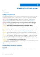
and tells you how to avoid the problem. WARNING: A WARNING indicates a potential for property damage, personal injury, or death. © 2020 - 2021 Dell Inc. or its subsidiaries. All rights reserved. Dell, EMC, and other trademarks are trademarks of Dell Inc. or its subsidiaries. Other trademarks may - Dell OptiPlex 5080 Tower | Service Manual - Page 3
Contents Chapter 1: Working on your computer 6 Safety instructions...6 Before working inside your computer...6 Safety precautions...7 Electrostatic discharge-ESD protection...7 ESD field service kit ...8 After working inside your computer...9 Chapter 2: Technology and components 10 Graphics - Dell OptiPlex 5080 Tower | Service Manual - Page 4
/Serial 59 Installing optional I/O modules (Type-C/HDMI/VGA/DP/Serial 60 System board...64 Removing the system board...64 Installing the system board...67 Chapter 4: Troubleshooting...71 4 Contents - Dell OptiPlex 5080 Tower | Service Manual - Page 5
Dell SupportAssist Pre-boot System Performance Check diagnostics 71 Running the SupportAssist Pre-Boot System Performance Check 71 Diagnostic LED behavior...72 Diagnostic error messages...73 System error messages...76 WiFi power cycle...76 Chapter 5: Getting help...77 Contacting Dell...77 - Dell OptiPlex 5080 Tower | Service Manual - Page 6
and the contacts. CAUTION: You should only perform troubleshooting and repairs as authorized or directed by the Dell technical assistance team. Damage due to servicing that is not authorized by Dell is not covered by your warranty. See the safety instructions that is shipped with the product or at - Dell OptiPlex 5080 Tower | Service Manual - Page 7
or reassembly: ● Turn off the system and all attached peripherals. ● Disconnect the system and all attached peripherals from AC power. ● Disconnect all network cables, telephone, and telecommunications lines from the system. ● Use an ESD field service kit when working inside any desktop to avoid - Dell OptiPlex 5080 Tower | Service Manual - Page 8
troubleshoot service kit The unmonitored Field Service kit is the most commonly used service kit. Each Field Service service service Service service Service desktop or portable environment. Servers are typically installed in a rack within a data center; desktops Dell, it is critical to place these - Dell OptiPlex 5080 Tower | Service Manual - Page 9
at all times when servicing Dell products. In addition, it is critical that technicians keep sensitive parts separate from all insulator parts while performing service and that they use anti-static bags for transporting sensitive components. After working inside your computer About this task CAUTION - Dell OptiPlex 5080 Tower | Service Manual - Page 10
USB type-C Alt mode: 4096 x 2304 @60 Hz ● Option VGA: 1920 x 1200 @60 Hz ● Option HDMI2.0: 4096 x 2160 @60 Hz Up to three displays supported ● Two motherboard integrated DP1.4 HBR2 + One video option (VGA/DP1.4 HBR2/HDMI2.0/USB3.2 Gen2 type-C Alt-mode) Two MB integrated DP1.4 HBR2 + One video option - Dell OptiPlex 5080 Tower | Service Manual - Page 11
: 4096 x 2304 @60 Hz ● Option VGA: 1920 x 1200 @60 Hz ● Option HDMI2.0: 4096 x 2160 @60 Hz Number of display supported Up to three displays supported Multiple Display Support ● Two motherboard integrated DP1.4 HBR2 + One video option (VGA/DP1.4 HBR2/HDMI2.0/USB3.2 Gen2 type-C Alt-mode) External - Dell OptiPlex 5080 Tower | Service Manual - Page 12
model Open CL Open GL GPU memory interface PCIe bus Display support Graphics memory configuration Graphics memory clock speed Active fan sink Slot Values 1.2 GHz 12 5.0 2.0 4.5 128 bit PCIe 3.0 x8 ● Two Mini DisplayPorts ● One DisplayPort 4 GB, GDDR5 7 Gbps 4-pin embedded fan controller - Dell OptiPlex 5080 Tower | Service Manual - Page 13
model Open CL Open GL GPU memory interface PCIe bus Display support Graphics memory configuration Graphics memory clock speed Active fan sink Slot toolkit available for download, for all Latitude Rugged tablets at dell.com/support, that automates and streamlines systems management tasks, saving time, - Dell OptiPlex 5080 Tower | Service Manual - Page 14
admins with an extensive inventory of the hardware and health-state data. Admins can also configure hardware remotely by using command line and scripting. Dell Command l Power Manager (end-user tool) is a GUI-based factory-installed battery management tool that allows end users to choose the battery - Dell OptiPlex 5080 Tower | Service Manual - Page 15
(Type C/ HDMI/VGA/DP/Serial) • System board Side cover Removing the side cover Prerequisites 1. Follow the procedure in before working inside your computer. NOTE: Ensure that you remove the security cable from the security-cable slot (if applicable). About this task The following images indicate the - Dell OptiPlex 5080 Tower | Service Manual - Page 16
Steps 1. Loosen the thumbscrew (#6-32) that secures the side cover to the computer. 2. Slide the side cover towards the rear of the computer and lift the cover away from the computer. 16 Disassembly and reassembly - Dell OptiPlex 5080 Tower | Service Manual - Page 17
Installing the side cover Prerequisites If you are replacing a component, remove the existing component before performing the installation procedure. About this task The following image indicates the location of the side cover and provides a visual representation of the installation procedure. - Dell OptiPlex 5080 Tower | Service Manual - Page 18
. Front bezel Removing the front bezel Prerequisites 1. Follow the procedure in before working inside your computer. 2. Remove the side cover. About this task The following images indicate the location of the front bezel and provide a visual representation of the removal procedure. - Dell OptiPlex 5080 Tower | Service Manual - Page 19
the front bezel and gently rotate to release the other tabs on the bezel from the slots in the computer chassis. 3. Remove the front bezel from the computer. Installing the front bezel Prerequisites If you are replacing a component, remove the existing component before performing the installation - Dell OptiPlex 5080 Tower | Service Manual - Page 20
. Steps 1. Press the retention tabs on both sides of the fan duct to release it. 2. Pull and remove the fan duct from the computer. Installing the fan duct Prerequisites If you are replacing a component, remove the existing component before performing the installation procedure. About this task The - Dell OptiPlex 5080 Tower | Service Manual - Page 21
. Hard-drive assembly Removing the 2.5-inch hard-disk drive assembly Prerequisites 1. Follow the procedure in before working inside your computer. 2. Remove the side cover. 3. Remove the fan duct. About this task The following images indicate the location of the 2.5-inch hard-disk drive assembly - Dell OptiPlex 5080 Tower | Service Manual - Page 22
drive so that you can replace it correctly. Removing the 2.5-inch hard-disk drive bracket Prerequisites 1. Follow the procedure in before working inside your computer. 2. Remove the side cover. 3. Remove the fan duct. 4. Remove the 2.5 in. hard-disk drive assembly. 22 Disassembly and reassembly - Dell OptiPlex 5080 Tower | Service Manual - Page 23
2.5 in. hard-disk drive assembly. 2. Install the fan duct. 3. Install the side cover. 4. Follow the procedure in after working inside your computer. Installing the 2.5-inch hard-disk drive assembly Prerequisites If you are replacing a component, remove the existing component before performing the - Dell OptiPlex 5080 Tower | Service Manual - Page 24
align back to insert the hard-disk drive assembly to the slot on the computer chassis. 3. Connect the hard-drive data and power cables to the connectors side cover. 3. Follow the procedure in after working inside your computer. 3.5-inch hard drive Removing the 3.5-inch hard-disk drive Prerequisites - Dell OptiPlex 5080 Tower | Service Manual - Page 25
2. Remove the side cover. 3. Remove the fan duct. About this task The following images indicate the location of the 3.5-inch hard-disk drive and provides a visual representation of the removal procedure. Steps 1. Disconnect the data and power cables from the connectors on the 3.5-inch hard-disk - Dell OptiPlex 5080 Tower | Service Manual - Page 26
connectors on the hard-disk drive module. Next steps 1. Install the fan duct. 2. Install the side cover. 3. Follow the procedure in after working inside your computer. Solid-state drive Removing the M.2 2230 PCIe solid-state drive Prerequisites 1. Follow the procedure in before working inside your - Dell OptiPlex 5080 Tower | Service Manual - Page 27
Steps 1. Remove the screw (M2x3.5) that secures the solid-state drive to the system board. 2. Slide and lift the solid-state drive off the system board. Installing the M.2 2230 PCIe solid-state drive Prerequisites If you are replacing a component, remove the existing component before performing the - Dell OptiPlex 5080 Tower | Service Manual - Page 28
. Removing the M.2 2280 PCIe solid-state drive Prerequisites 1. Follow the procedure in before working inside your computer. 2. Remove the side cover. 3. Remove the fan duct. About this task The following images indicate the location of the solid-state drive and provide a visual - Dell OptiPlex 5080 Tower | Service Manual - Page 29
Steps 1. Remove the screw (M2x3.5) that secures the solid-state drive to the system board. 2. Slide and lift the solid-state drive off the system board. Installing the M.2 2280 PCIe solid-state drive Prerequisites If you are replacing a component, remove the existing component before performing the - Dell OptiPlex 5080 Tower | Service Manual - Page 30
fan duct. 2. Install the side cover. 3. Follow the procedure in after working inside your computer. Memory modules Removing the memory modules Prerequisites 1. Follow the procedure in before working inside your computer. 2. Remove the side cover. 3. Remove the fan duct. About this task The following - Dell OptiPlex 5080 Tower | Service Manual - Page 31
Steps 1. Pull the securing clips from both side of the memory module until the memory module pops up. 2. Slide and remove the memory module from the memory-module slot. Installing the memory modules Prerequisites If you are replacing a component, remove the existing component before performing the - Dell OptiPlex 5080 Tower | Service Manual - Page 32
the side cover. 3. Follow the procedure in after working inside your computer. SD card reader (optional) Removing the SD card reader Prerequisites 1. Follow the procedure in before working inside your computer. 2. Remove the side cover. 3. Remove the fan duct. About - Dell OptiPlex 5080 Tower | Service Manual - Page 33
2. Remove the (M2x3.5) screw that secures the card reader to the SD card slot. 3. Slide and remove the SD card reader from the connector on the system board. Installing the SD card reader Prerequisites If you are replacing a component, remove the existing component before performing the installation - Dell OptiPlex 5080 Tower | Service Manual - Page 34
. Processor fan and heat-sink assembly Removing the processor fan and heat-sink assembly Prerequisites 1. Follow the procedure in before working inside your computer. WARNING: The heat sink may become hot during normal operation. Allow sufficient time for the heat sink to cool before you touch it - Dell OptiPlex 5080 Tower | Service Manual - Page 35
to the connector on the system board. Next steps 1. Install the fan duct. 2. Install the side cover. 3. Follow the procedure in after working inside your computer. Disassembly and reassembly 35 - Dell OptiPlex 5080 Tower | Service Manual - Page 36
the side cover. 3. Remove the fan duct. 4. Remove the processor fan and heat-sink assembly. NOTE: The processor might still be hot after the computer is shut down. Allow the processor to cool down before removing it. About this task The following images indicate the location of the processor and - Dell OptiPlex 5080 Tower | Service Manual - Page 37
2. Lift the lever upward to lift the processor cover. CAUTION: When removing the processor, do not touch any of the pins inside the socket or allow any objects to fall on the pins in the socket. 3. Gently lift the processor from the processor socket. Installing the processor Prerequisites If you are - Dell OptiPlex 5080 Tower | Service Manual - Page 38
fan duct. 3. Install the side cover. 4. Follow the procedure in after working inside your computer. Graphics card Removing the graphics card Prerequisites 1. Follow the procedure in before working inside your computer. 2. Remove the side cover. 3. Remove the fan duct. About this task The following - Dell OptiPlex 5080 Tower | Service Manual - Page 39
Steps 1. Locate the graphics card (PCI-Express). 2. Lift the pull tab to open the PCIe door. 3. Push and hold the securing tab on the graphics-card slot and lift the graphics card from the graphics-card slot. Installing the graphics card Prerequisites If you are replacing a component, remove the - Dell OptiPlex 5080 Tower | Service Manual - Page 40
pull tab to close the PCIe door. Next steps 1. Install the fan duct. 2. Install the side cover. 3. Follow the procedure in after working inside your computer. Graphical processing unit Removing the powered GPU Prerequisites 1. Follow the procedure in before working inside your - Dell OptiPlex 5080 Tower | Service Manual - Page 41
. 3. Follow the procedure in after working inside your computer. Coin-cell battery Removing the coin-cell battery Prerequisites 1. Follow the procedure in before working inside your computer. 2. Remove the side cover. 3. Remove the fan duct. 4. - Dell OptiPlex 5080 Tower | Service Manual - Page 42
, gently pry the coin-cell battery out of the slot on the system board. 2. Remove the coin-cell battery away from the computer. Installing the coin-cell battery Prerequisites If you are replacing a component, remove the existing component before performing the installation procedure. About this - Dell OptiPlex 5080 Tower | Service Manual - Page 43
fan duct. 3. Install the side cover. 4. Follow the procedure in after working inside your computer. WLAN card Removing the WLAN card Prerequisites 1. Follow the procedure in before working inside your computer. 2. Remove the side cover. 3. Remove the fan duct. 4. Remove the powered GPU. NOTE: This - Dell OptiPlex 5080 Tower | Service Manual - Page 44
Steps 1. Remove the (M2x3.5) screw that secures the WLAN card to the system board. 2. Lift the WLAN card bracket away from the WLAN card. 3. Disconnect the antenna cables from the WLAN card. 4. Slide and remove the WLAN card from the connector on the system board. Installing the WLAN card - Dell OptiPlex 5080 Tower | Service Manual - Page 45
the antenna cables to the WLAN card. The following table provides the antenna-cable color scheme for the WLAN card of your computer. Table 6. Antenna-cable color scheme Connectors on the wireless card Main (white triangle) Antenna-cable color White Auxiliary (black triangle) Black 2. Place - Dell OptiPlex 5080 Tower | Service Manual - Page 46
Slim optical-drive Removing the Slim-Optical Disk Drive Prerequisites 1. Follow the procedure in before working inside your computer. 2. Remove the side cover. 3. Remove the fan duct. About this task The following images indicate the location of the slim ODD and provides a visual representation - Dell OptiPlex 5080 Tower | Service Manual - Page 47
snaps into place. 3. Route the power cable and data cable through the routing guides and connect the cables to the slim ODD. Next steps 1. Install the fan bracket Prerequisites 1. Follow the procedure in before working inside your computer. 2. Remove the side cover. 3. Remove the fan duct. - Dell OptiPlex 5080 Tower | Service Manual - Page 48
Steps 1. Pry the slim-ODD bracket to release it from the slot on the ODD. 2. Remove the slim-ODD bracket off the ODD. Installing the slim-ODD bracket Prerequisites If you are replacing a component, remove the existing component before performing the installation procedure. About this task The - Dell OptiPlex 5080 Tower | Service Manual - Page 49
. Voltage regulator heat sink Removing the VR heat sink Prerequisites 1. Follow the procedure in before working inside your computer. WARNING: The heat sink may become hot during normal operation. Allow sufficient time for the heat sink to cool before you touch it. CAUTION: For - Dell OptiPlex 5080 Tower | Service Manual - Page 50
in after working inside your computer. Speaker Removing the speaker Prerequisites 1. Follow the procedure in before working inside your computer. 2. Remove the side on the system board. 2. Unroute the speaker cable from the routing guides on the chassis. 3. Press the tab and slide the speaker along - Dell OptiPlex 5080 Tower | Service Manual - Page 51
chassis until it snaps into place. 2. Route the speaker cable through the routing guide on the chassis. 3. Connect the speaker cable to the connector on the system the procedure in after working inside your computer. Power button Removing the power button Prerequisites 1. Follow the procedure in - Dell OptiPlex 5080 Tower | Service Manual - Page 52
the power-button head and slide the power-button cable out from the front-side chassis of the computer. 3. Pull the power-button cable out from the computer. Installing the power button Prerequisites If you are replacing a component, remove the existing component before performing the installation - Dell OptiPlex 5080 Tower | Service Manual - Page 53
the side cover. 4. Follow the procedure in after working inside your computer. Power-supply unit Removing the power-supply unit Prerequisites 1. Follow the procedure in before working inside your computer. 2. Remove the side cover. 3. Remove the fan duct. - Dell OptiPlex 5080 Tower | Service Manual - Page 54
54 Disassembly and reassembly - Dell OptiPlex 5080 Tower | Service Manual - Page 55
Steps 1. Lay the computer on the right side. 2. Disconnect the power cables from the system board and unroute them from the routing guides on the chassis. 3. Remove the three (#6-32) screws that secure the power-supply unit to the chassis. 4. Press the securing clip and slide the power- - Dell OptiPlex 5080 Tower | Service Manual - Page 56
56 Disassembly and reassembly - Dell OptiPlex 5080 Tower | Service Manual - Page 57
unit to the chassis. 3. Route the power cable through the routing guides on the chassis and connect the power cables to their respective connectors on inside your computer. Intrusion switch Removing the intrusion switch Prerequisites 1. Follow the procedure in before working inside your computer. 2. - Dell OptiPlex 5080 Tower | Service Manual - Page 58
Steps 1. Disconnect the intruder cable from the connector on the system board. 2. Slide and remove the intrusion switch from the chassis. Installing the intrusion switch Prerequisites If you are replacing a component, remove the existing component before performing the installation procedure. About - Dell OptiPlex 5080 Tower | Service Manual - Page 59
the system board. Next steps 1. Install the fan duct. 2. Install the side cover. 3. Follow the procedure in after working inside your computer. Optional I/O modules (Type C/ HDMI/VGA/DP/Serial) Removing optional I/O modules (Type C/ HDMI/VGA/DP/Serial) Prerequisites 1. Follow the procedure in before - Dell OptiPlex 5080 Tower | Service Manual - Page 60
3. Remove the I/O module from the computer. Installing optional I/O modules (Type-C/HDMI/VGA/DP/Serial) Prerequisites If you are replacing a component, remove the existing component before performing the installation procedure. About this - Dell OptiPlex 5080 Tower | Service Manual - Page 61
Disassembly and reassembly 61 - Dell OptiPlex 5080 Tower | Service Manual - Page 62
62 Disassembly and reassembly - Dell OptiPlex 5080 Tower | Service Manual - Page 63
lift the bracket out from the system. 2. Insert the optional I/O module (Type-C/HDMI/VGA/DP/Serial) into its slot from the inside of your computer. 3. Connect the I/O cable to the connector on the system board . 4. Replace the two (M3X3) screws to secure the optional I/O module to the system. Next - Dell OptiPlex 5080 Tower | Service Manual - Page 64
System board Removing the system board Prerequisites 1. Follow the procedure in before working inside your computer. NOTE: Your computer's Service Tag is stored in the system board. You must enter the Service Tag in the BIOS setup program after you replace the system board. NOTE: Replacing the - Dell OptiPlex 5080 Tower | Service Manual - Page 65
Disassembly and reassembly 65 - Dell OptiPlex 5080 Tower | Service Manual - Page 66
Steps 1. Remove the two (#6-32) screws that secure the front I/O-bracket to the chassis. 2. Slide and remove the front I/O-bracket from the chassis. 3. Disconnect all the cables that are connected to the system board. 4. Remove the M.2 card standoff (#6-32) screw and eight (#6-32) screws that secure - Dell OptiPlex 5080 Tower | Service Manual - Page 67
5. Lift the system board at an angle and remove the system board off the chassis. Installing the system board Prerequisites If you are replacing a component, remove the existing component before performing the installation procedure. About this task The following images indicate the location of the - Dell OptiPlex 5080 Tower | Service Manual - Page 68
68 Disassembly and reassembly - Dell OptiPlex 5080 Tower | Service Manual - Page 69
Steps 1. Slide the front I/O-ports on the system board into the front I/O-slots on the chassis and align the screw holes on the system board with the screw holes on the chassis. 2. Replace the M.2 card standoff (#6-32) screw and eight (#6-32) screws that secure the system board to the chassis. 3. - Dell OptiPlex 5080 Tower | Service Manual - Page 70
the front bezel. 10. Install the side cover. 11. Follow the procedure in after working inside your computer. NOTE: Your computer's Service Tag is stored in the system board. You must enter the Service Tag in the BIOS setup program after you replace the system board. NOTE: Replacing the system board - Dell OptiPlex 5080 Tower | Service Manual - Page 71
tests are performed. For more information, see https://www.dell.com/support/kbdoc/000180971. Running the SupportAssist Pre-Boot System Performance Check Steps 1. Turn on your computer. 2. As the computer boots, press the F12 key as the Dell logo appears. 3. On the boot menu screen, select the - Dell OptiPlex 5080 Tower | Service Manual - Page 72
SPI Flash Failure CPU failure ● Run the Dell Support Assist/Dell Diagnostics tool. ● If problem persists, replace the system board. System board failure (included ● BIOS corruption or ROM ● error) Flash latest BIOS version If problem persists, replace the system board. No memory - Dell OptiPlex 5080 Tower | Service Manual - Page 73
waiting on ME to reply to HECI message ● If problem persists, replace the system board. CPU Power Cable does not match the memory module installed in the computer. Restart the computer. If the error appears again, Contact Dell The file that you are trying to copy is . Troubleshooting 73 - Dell OptiPlex 5080 Tower | Service Manual - Page 74
computer. If the problem persists, try another drive. Run the Hard Disk Drive tests in Dell Diagnostics. HARD-DISK DRIVE FAILURE The hard drive does not respond to commands from the computer. Shut down the computer program, or a utility. Shut down the computer, wait for 30 seconds, and then restart - Dell OptiPlex 5080 Tower | Service Manual - Page 75
hard drive. See Windows Help and Support for instructions (click Start > Help and Support). If a large number of sectors are supports the system configuration settings may require recharging. Connect your computer to an electrical outlet to charge the battery. If the problem persists, Contact Dell - Dell OptiPlex 5080 Tower | Service Manual - Page 76
: NOTE: Some ISPs (Internet Service Providers) provide a modem/router combo device. Steps 1. Turn off your computer. 2. Turn off the modem. 3. Turn off the wireless router. 4. Wait for 30 seconds. 5. Turn on the wireless router. 6. Turn on the modem. 7. Turn on your computer. 76 Troubleshooting - Dell OptiPlex 5080 Tower | Service Manual - Page 77
. Availability varies by country and product, and some services may not be available in your area. To contact Dell for sales, technical support, or customer service issues: Steps 1. Go to Dell.com/support. 2. Select your support category. 3. Verify your country or region in the Choose a Country
-
 1
1 -
 2
2 -
 3
3 -
 4
4 -
 5
5 -
 6
6 -
 7
7 -
8
-
9
-
10
-
11
-
12
-
13
-
14
-
15
-
16
-
17
-
18
-
19
-
20
-
21
-
22
-
23
-
24
-
25
-
26
-
27
-
28
-
29
-
30
-
31
-
32
-
33
-
34
-
35
-
36
-
37
-
38
-
39
-
40
-
41
-
42
-
43
-
44
-
45
-
46
-
47
-
48
-
49
-
50
-
51
-
52
-
53
-
54
-
55
-
56
-
57
-
58
-
59
-
60
-
61
-
62
-
63
-
64
-
65
-
66
-
67
-
68
-
69
-
70
-
71
-
72
-
73
-
74
-
75
-
76
-
77
 |
 |

OptiPlex 5080 Tower
Service Manual
Regulatory Model: D29M
Regulatory Type: D29M001
May 2020
Rev. A00