Dell OptiPlex 9030 All In One Dell OptiPlex 9030 All-In-One Owners Manual - Page 29
Installing the I/O Board Shield, Removing the Power Supply Unit (PSU
 |
View all Dell OptiPlex 9030 All In One manuals
Add to My Manuals
Save this manual to your list of manuals |
Page 29 highlights
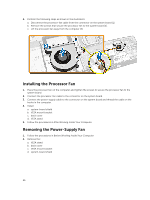
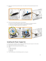
5. Remove the screws that secure the I/O board shield to the chassis. Loosen the power connector and press it down the socket. Flip the input/output (I/O) board shield and remove it from the computer. Installing the I/O Board Shield 1. Place the I/O board shield on the computer. 2. Pass the power connector and fix it to the socket. Tighten the screws that secure the I/O board shield to the chassis. 3. Tighten the screws that secure the power connector to the I/O board shield. 4. Tighten the screws that secure the power-button board to the I/O board shield. 5. Place the I/O panel on the computer. 6. Install: a. power-supply fan b. system-board shield c. VESA mount bracket d. back cover e. speaker cover f. VESA stand 7. Follow the procedures in After Working Inside Your Computer. Removing the Power Supply Unit (PSU) 1. Follow the procedures in Before Working Inside Your Computer. 2. Remove the: a. VESA stand b. back cover c. VESA mount bracket d. system-board shield e. input/output (I/O) board shield f. power-supply fan 29
-
 1
1 -
2
-
3
-
4
-
5
-
6
-
7
-
8
-
9
-
10
-
11
-
12
-
13
-
14
-
15
-
16
-
17
-
18
-
19
-
20
-
21
-
22
-
23
-
 24
24 -
 25
25 -
 26
26 -
 27
27 -
 28
28 -
 29
29 -
 30
30 -
 31
31 -
 32
32 -
 33
33 -
 34
34 -
35
-
36
-
37
-
38
-
39
-
40
-
41
-
42
-
43
-
44
-
45
-
46
-
47
-
48
-
49
-
50
-
51
-
52
-
53
-
54
-
55
-
56
-
57
-
58
-
59
-
60
-
61
 |
 |
