Dell OptiPlex 9030 All In One Dell OptiPlex 9030 All-In-One Owners Manual - Page 37
Removing the Display Panel - disassembly
 |
View all Dell OptiPlex 9030 All In One manuals
Add to My Manuals
Save this manual to your list of manuals |
Page 37 highlights
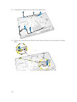
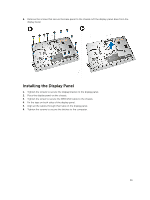
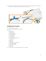
Removing the Display Panel 1. Follow the procedures in Before Working Inside Your Computer. 2. Remove the: a. VESA stand b. back cover c. VESA mount bracket d. system-board shield e. input/output (I/O) board shield f. WLAN card g. optical drive h. hard drive i. intrusion switch j. power and OSD buttons board k. converter board l. power-supply fan m. power supply unit n. heatsink assembly o. processor fan p. speakers q. speaker cover r. antenna module s. system board NOTE: These instructions are valid only for non-touch computers. For touch computers, the display panel should be disassembled in a clean-room environment. 3. Perform the following steps as shown in the illustration: a. Remove the screws that secure the release latch holders to the display-panel base [1] . b. Lift the release latch holders off the display-panel base [2]. c. Remove the screws that secure the release latch brackets to the display-panel base [3]. d. Lift the release latch brackets off the display-panel base [4]. e. Rotate and lift the release latch lock brackets off the display-panel base [5]. 37
-
 1
1 -
2
-
3
-
4
-
5
-
6
-
7
-
8
-
9
-
10
-
11
-
12
-
13
-
14
-
15
-
16
-
17
-
18
-
19
-
20
-
21
-
22
-
23
-
24
-
25
-
26
-
27
-
28
-
29
-
30
-
31
-
 32
32 -
 33
33 -
 34
34 -
 35
35 -
 36
36 -
 37
37 -
 38
38 -
 39
39 -
 40
40 -
 41
41 -
 42
42 -
43
-
44
-
45
-
46
-
47
-
48
-
49
-
50
-
51
-
52
-
53
-
54
-
55
-
56
-
57
-
58
-
59
-
60
-
61
 |
 |
