Dell OptiPlex 9030 All In One Dell OptiPlex 9030 All-In-One Owners Manual - Page 35
System Board Layout, Lift the system board away from the computer [3].
 |
View all Dell OptiPlex 9030 All In One manuals
Add to My Manuals
Save this manual to your list of manuals |
Page 35 highlights
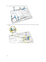
4. Perform the following steps as shown in the illustration. a. Remove the screws that secure the system board to the computer [1]. b. Slide the system board to release it from the computer [2]. c. Lift the system board away from the computer [3]. 5. Lift and remove the system board from the chassis. System Board Layout The following image displays the system board layout of the computer. 1. processor socket 2. WLAN connector 3. coin-cell battery 35
-
 1
1 -
2
-
3
-
4
-
5
-
6
-
7
-
8
-
9
-
10
-
11
-
12
-
13
-
14
-
15
-
16
-
17
-
18
-
19
-
20
-
21
-
22
-
23
-
24
-
25
-
26
-
27
-
28
-
29
-
 30
30 -
 31
31 -
 32
32 -
 33
33 -
 34
34 -
 35
35 -
 36
36 -
 37
37 -
 38
38 -
 39
39 -
 40
40 -
41
-
42
-
43
-
44
-
45
-
46
-
47
-
48
-
49
-
50
-
51
-
52
-
53
-
54
-
55
-
56
-
57
-
58
-
59
-
60
-
61
 |
 |

4.
Perform the following steps as shown in the illustration.
a.
Remove the screws that secure the system board to the computer [1].
b.
Slide the system board to release it from the computer [2].
c.
Lift the system board away from the computer [3].
5.
Lift and remove the system board from the chassis.
System Board Layout
The following image displays the system board layout of the computer.
1.
processor socket
2.
WLAN connector
3.
coin-cell battery
35