Dell PowerEdge 1655MC System Configuration Guide - Page 12
module, perform the following steps, Perform steps 1 through 14 in Configuring the Client System.
 |
View all Dell PowerEdge 1655MC manuals
Add to My Manuals
Save this manual to your list of manuals |
Page 12 highlights
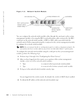
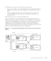
www.dell.com | support.dell.com Figure 1-4. Network Switch Module link indicators (4) activity indicators (4) reset button RJ11 serial port for network switch module setup 10/100/1000 BASE-T uplink ports (4) system fault indicator You can configure the network switch module either through the serial port on the system management module or by using the RJ11 serial null modem cable connected to the RJ11 serial port on the network switch module. A DB9-to-RJ11 cable is provided with the network switch. Dell recommends using the serial port on the system management module to configure the network switch module. NOTE: Do not connect the RJ11 configuration port to a data or telephone network. Do not connect the RJ11 serial cable to any of the 10/100/1000 BASE-T uplink ports. To configure the network switch module using the serial port on the system management module, perform the following steps: 1 Perform steps 1 through 14 in "Configuring the Client System." 2 After you have logged into the remote access portion of the system management module, select one of the network switch modules. • Type connect switch-1 to connect to the top network switch module. • Type connect switch-2 to connect to the bottom network switch module. 3 To log on to the network switch module console, type: Username-admin Password-admin You are logged into the switch console. By default, the switch is DHCP client-enabled. 4 To obtain the IP address of the network switch module, type #sh ip interface. 1-8 System Configuration Guide
-
 1
1 -
2
-
3
-
4
-
5
-
6
-
 7
7 -
 8
8 -
 9
9 -
 10
10 -
 11
11 -
 12
12 -
 13
13 -
 14
14 -
 15
15 -
 16
16 -
 17
17 -
18
-
19
-
20
-
21
-
22
-
23
-
24
-
25
-
26
-
27
-
28
-
29
-
30
-
31
-
32
-
33
-
34
-
35
-
36
-
37
-
38
-
39
-
40
-
41
-
42
-
43
-
44
-
45
-
46
-
47
-
48
-
49
-
50
-
51
-
52
-
53
-
54
-
55
-
56
-
57
-
58
-
59
-
60
-
61
-
62
-
63
-
64
-
65
-
66
-
67
-
68
-
69
-
70
-
71
-
72
-
73
-
74
-
75
-
76
-
77
-
78
-
79
-
80
-
81
-
82
-
83
-
84
-
85
-
86
-
87
-
88
-
89
-
90
-
91
-
92
-
93
-
94
-
95
-
96
-
97
-
98
-
99
-
100
-
101
-
102
-
103
-
104
-
105
-
106
-
107
-
108
-
109
-
110
-
111
-
112
-
113
-
114
-
115
-
116
-
117
-
118
-
119
-
120
-
121
-
122
-
123
-
124
-
125
-
126
-
127
-
128
-
129
-
130
-
131
-
132
-
133
-
134
-
135
-
136
-
137
-
138
-
139
-
140
-
141
-
142
-
143
-
144
-
145
-
146
-
147
-
148
-
149
-
150
-
151
-
152
-
153
-
154
-
155
-
156
-
157
-
158
-
159
-
160
-
161
-
162
-
163
-
164
-
165
-
166
-
167
-
168
-
169
-
170
-
171
-
172
-
173
-
174
-
175
-
176
-
177
-
178
-
179
-
180
-
181
-
182
-
183
-
184
-
185
-
186
-
187
-
188
-
189
-
190
-
191
-
192
-
193
-
194
-
195
-
196
-
197
-
198
-
199
-
200
-
201
-
202
-
203
-
204
-
205
-
206
-
207
-
208
-
209
-
210
-
211
-
212
-
213
-
214
-
215
-
216
-
217
-
218
-
219
-
220
-
221
-
222
-
223
 |
 |
