Dell PowerEdge 1655MC System Configuration Guide - Page 16
Configuring a Static Channel, Link Aggregation
 |
View all Dell PowerEdge 1655MC manuals
Add to My Manuals
Save this manual to your list of manuals |
Page 16 highlights
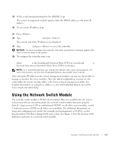
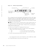
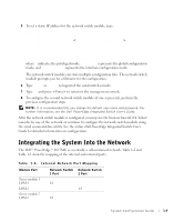
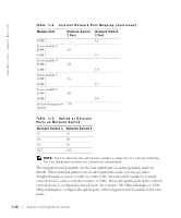
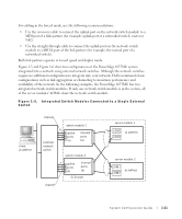
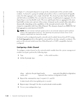
www.dell.com | support.dell.com In Figure 1-5, a four-port channel is set up on the external ports of the network switch modules. A channel is a group of multiple physical lines where a control protocol logically makes the links aggregate into a single virtual link. The channel provides high bandwidth and link failover availability. You can select the number of uplink ports to aggregate (2 to 4) depending on your bandwidth needs. The more uplink ports that are aggregated, the more bandwidth you have into and out of the system. A channel can be created either statically or dynamically, depending on the capabilities of the external network switch. The static channel is compatible with Cisco EtherChannel. The dynamic channel uses IEEE 802.3ad link aggregation control protocol (LACP). NOTE: Do not connect multiple uplink ports to an external network switch without using a link aggregation protocol. The spanning tree protocol blocks three of the network connections to resolve the loops. A channel can be configured using the network switch module browser-based GUI (using the Link Aggregation tab) or through the command-line interface using the serial port. The ports on the external switch must have EtherChannel- or LACP- compatible channels configured. Configuring a Static Channel To configure a static channel on the network switch module from the system management module serial port, perform the following steps: 1 Type connect switch-x, where x is the switch number. 2 At the # prompt, type: #Config (config)#interface port-channel 1 (config-if)#exit (config)#interface ethernet 1/7 (config-if)#channel-group 1 (config)#exit where # indicates the privileged mode, (config) represents the global configuration mode, and (config-if) represents the interface configuration mode. 3 Repeat the commands in step 2 on ports 8, 9, and 10. A static trunk of the four uplink ports is created. 4 Repeat steps 1 through 3 for the second network switch module. 5 To save your configuration, type #copy running-config startup-config. 1-12 System Configuration Guide
-
 1
1 -
2
-
3
-
4
-
5
-
6
-
7
-
8
-
9
-
10
-
 11
11 -
 12
12 -
 13
13 -
 14
14 -
 15
15 -
 16
16 -
 17
17 -
 18
18 -
 19
19 -
 20
20 -
 21
21 -
22
-
23
-
24
-
25
-
26
-
27
-
28
-
29
-
30
-
31
-
32
-
33
-
34
-
35
-
36
-
37
-
38
-
39
-
40
-
41
-
42
-
43
-
44
-
45
-
46
-
47
-
48
-
49
-
50
-
51
-
52
-
53
-
54
-
55
-
56
-
57
-
58
-
59
-
60
-
61
-
62
-
63
-
64
-
65
-
66
-
67
-
68
-
69
-
70
-
71
-
72
-
73
-
74
-
75
-
76
-
77
-
78
-
79
-
80
-
81
-
82
-
83
-
84
-
85
-
86
-
87
-
88
-
89
-
90
-
91
-
92
-
93
-
94
-
95
-
96
-
97
-
98
-
99
-
100
-
101
-
102
-
103
-
104
-
105
-
106
-
107
-
108
-
109
-
110
-
111
-
112
-
113
-
114
-
115
-
116
-
117
-
118
-
119
-
120
-
121
-
122
-
123
-
124
-
125
-
126
-
127
-
128
-
129
-
130
-
131
-
132
-
133
-
134
-
135
-
136
-
137
-
138
-
139
-
140
-
141
-
142
-
143
-
144
-
145
-
146
-
147
-
148
-
149
-
150
-
151
-
152
-
153
-
154
-
155
-
156
-
157
-
158
-
159
-
160
-
161
-
162
-
163
-
164
-
165
-
166
-
167
-
168
-
169
-
170
-
171
-
172
-
173
-
174
-
175
-
176
-
177
-
178
-
179
-
180
-
181
-
182
-
183
-
184
-
185
-
186
-
187
-
188
-
189
-
190
-
191
-
192
-
193
-
194
-
195
-
196
-
197
-
198
-
199
-
200
-
201
-
202
-
203
-
204
-
205
-
206
-
207
-
208
-
209
-
210
-
211
-
212
-
213
-
214
-
215
-
216
-
217
-
218
-
219
-
220
-
221
-
222
-
223
 |
 |
