Dell PowerEdge 1655MC System Configuration Guide - Page 5
you can use for system setup and configuration. shows the drive shelf attached so, addition - blade
 |
View all Dell PowerEdge 1655MC manuals
Add to My Manuals
Save this manual to your list of manuals |
Page 5 highlights
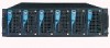
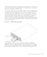
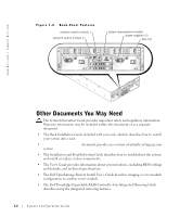
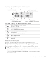
This guide provides information on configuring your system and the server modules in your system. The guide provides a starting point for system configuration; however, additional information is available from additional sources. Your system can include up to six server modules (or blades). Each server module functions as an individual system encompassing up to two microprocessors, up to two hard drives, and up to two memory modules. To function as a system, a server module is inserted into a system that includes power supplies, fans, a system management module, and at least one network switch module. The power supplies, fans, system management module, and network switch module are shared resources of the server modules in the system. In addition, your system may also ship with a USB diskette drive and a USB CD drive, which you can use for system setup and configuration. Figure 1-1 shows the drive shelf attached so that you can load software. Figure 1-1. System With Drive Shelf drive shelf USB CD drive The network switch module and a system management module require additional configuration. The system management module contains the keyboard, video, and mouse (KVM) switch and the embedded remote access circuitry and firmware used to configure systems management software. Figure 1-2 shows the location of the back-panel features. System Configuration Guide 1-1
-
 1
1 -
 2
2 -
 3
3 -
 4
4 -
 5
5 -
 6
6 -
 7
7 -
 8
8 -
 9
9 -
 10
10 -
 11
11 -
12
-
13
-
14
-
15
-
16
-
17
-
18
-
19
-
20
-
21
-
22
-
23
-
24
-
25
-
26
-
27
-
28
-
29
-
30
-
31
-
32
-
33
-
34
-
35
-
36
-
37
-
38
-
39
-
40
-
41
-
42
-
43
-
44
-
45
-
46
-
47
-
48
-
49
-
50
-
51
-
52
-
53
-
54
-
55
-
56
-
57
-
58
-
59
-
60
-
61
-
62
-
63
-
64
-
65
-
66
-
67
-
68
-
69
-
70
-
71
-
72
-
73
-
74
-
75
-
76
-
77
-
78
-
79
-
80
-
81
-
82
-
83
-
84
-
85
-
86
-
87
-
88
-
89
-
90
-
91
-
92
-
93
-
94
-
95
-
96
-
97
-
98
-
99
-
100
-
101
-
102
-
103
-
104
-
105
-
106
-
107
-
108
-
109
-
110
-
111
-
112
-
113
-
114
-
115
-
116
-
117
-
118
-
119
-
120
-
121
-
122
-
123
-
124
-
125
-
126
-
127
-
128
-
129
-
130
-
131
-
132
-
133
-
134
-
135
-
136
-
137
-
138
-
139
-
140
-
141
-
142
-
143
-
144
-
145
-
146
-
147
-
148
-
149
-
150
-
151
-
152
-
153
-
154
-
155
-
156
-
157
-
158
-
159
-
160
-
161
-
162
-
163
-
164
-
165
-
166
-
167
-
168
-
169
-
170
-
171
-
172
-
173
-
174
-
175
-
176
-
177
-
178
-
179
-
180
-
181
-
182
-
183
-
184
-
185
-
186
-
187
-
188
-
189
-
190
-
191
-
192
-
193
-
194
-
195
-
196
-
197
-
198
-
199
-
200
-
201
-
202
-
203
-
204
-
205
-
206
-
207
-
208
-
209
-
210
-
211
-
212
-
213
-
214
-
215
-
216
-
217
-
218
-
219
-
220
-
221
-
222
-
223
 |
 |
