Dell PowerEdge 1655MC System Configuration Guide - Page 15
Both link partners operate in forced speed and duplex mode.
 |
View all Dell PowerEdge 1655MC manuals
Add to My Manuals
Save this manual to your list of manuals |
Page 15 highlights
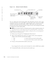
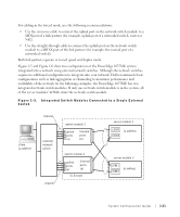
For cabling in the forced mode, use the following recommendations: • Use the crossover cable to connect the uplink port on the network switch module to a MDI port of a link partner (for example, uplink port of a networked switch, router or NIC). • Use the straight-through cable to connect the uplink port on the network switch module to a MID-X port of the link partner (for example, the normal port of a networked switch). Both link partners operate in forced speed and duplex mode. Figure 1-5 and Figure 1-6 show two configurations of the PowerEdge 1655MC system integrated into a network using external network switches. Although the network switches require no additional configuration to integrate into your network, Dell recommends basic configurations such as link aggregation or channeling to maximize performance and availability of the network. In the following examples, the PowerEdge 1655MC has two integrated network switch modules. If only one network switch module is in the system, all of the server modules' LOM1s share the network switch module. Figure 1-5. Integrated Switch Modules Connected to a Single External Switch client ip address channel external network switch channel switch module 1 uplink ports (4) internal ports (6) switch module 2 uplink ports (4) internal ports (6) SLB team server module 1 LOM1 ip address LOM2 server module 2 LOM1 ip address LOM2 System Configuration Guide 1-11
-
 1
1 -
2
-
3
-
4
-
5
-
6
-
7
-
8
-
9
-
 10
10 -
 11
11 -
 12
12 -
 13
13 -
 14
14 -
 15
15 -
 16
16 -
 17
17 -
 18
18 -
 19
19 -
 20
20 -
21
-
22
-
23
-
24
-
25
-
26
-
27
-
28
-
29
-
30
-
31
-
32
-
33
-
34
-
35
-
36
-
37
-
38
-
39
-
40
-
41
-
42
-
43
-
44
-
45
-
46
-
47
-
48
-
49
-
50
-
51
-
52
-
53
-
54
-
55
-
56
-
57
-
58
-
59
-
60
-
61
-
62
-
63
-
64
-
65
-
66
-
67
-
68
-
69
-
70
-
71
-
72
-
73
-
74
-
75
-
76
-
77
-
78
-
79
-
80
-
81
-
82
-
83
-
84
-
85
-
86
-
87
-
88
-
89
-
90
-
91
-
92
-
93
-
94
-
95
-
96
-
97
-
98
-
99
-
100
-
101
-
102
-
103
-
104
-
105
-
106
-
107
-
108
-
109
-
110
-
111
-
112
-
113
-
114
-
115
-
116
-
117
-
118
-
119
-
120
-
121
-
122
-
123
-
124
-
125
-
126
-
127
-
128
-
129
-
130
-
131
-
132
-
133
-
134
-
135
-
136
-
137
-
138
-
139
-
140
-
141
-
142
-
143
-
144
-
145
-
146
-
147
-
148
-
149
-
150
-
151
-
152
-
153
-
154
-
155
-
156
-
157
-
158
-
159
-
160
-
161
-
162
-
163
-
164
-
165
-
166
-
167
-
168
-
169
-
170
-
171
-
172
-
173
-
174
-
175
-
176
-
177
-
178
-
179
-
180
-
181
-
182
-
183
-
184
-
185
-
186
-
187
-
188
-
189
-
190
-
191
-
192
-
193
-
194
-
195
-
196
-
197
-
198
-
199
-
200
-
201
-
202
-
203
-
204
-
205
-
206
-
207
-
208
-
209
-
210
-
211
-
212
-
213
-
214
-
215
-
216
-
217
-
218
-
219
-
220
-
221
-
222
-
223
 |
 |
