Dell PowerEdge 1655MC System Configuration Guide - Page 14
Table, Uplink or External, Ports on Network Switch, Network Switch 1, Internal Network Port Mapping
 |
View all Dell PowerEdge 1655MC manuals
Add to My Manuals
Save this manual to your list of manuals |
Page 14 highlights
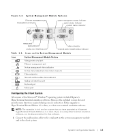
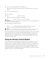
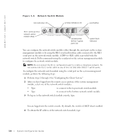
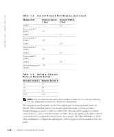
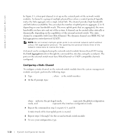
www.dell.com | support.dell.com Table 1-2. Internal Network Port Mapping (continued) Module Port LOM 2 Server module 3 LOM 1 LOM 2 Server module 4 LOM 1 LOM 2 Server module 5 LOM 1 LOM 2 Server module 6 LOM 1 LOM 2 System management module Network Switch 1 Port 1/3 1/4 1/5 1/6 1/11 Network Switch 2 Port 1/2 1/3 1/4 1/5 1/6 Table 1-3. Uplink or External Ports on Network Switch Network Switch 1 Network Switch 2 1/7 1/7 1/8 1/8 1/9 1/9 1/10 1/10 NOTE: The 1/x indicates the switch port number x under the CLI console interface. The two integrated switches are completely independent. The integrated switch module sets the four uplink ports in autonegotiation mode by default. When both link partners are in autonegotiation mode, you can use either straight-through or crossover cables to connect the network switch module to external network devices, such as switches, routers, or NICs. When the uplink ports of the external network device is configured in forced mode (for example, 100 Mbps full-duplex or 1000 Mbps full-duplex), configure the uplink ports of the integrated switch module in the same mode. 1-10 System Configuration Guide
-
 1
1 -
2
-
3
-
4
-
5
-
6
-
7
-
8
-
 9
9 -
 10
10 -
 11
11 -
 12
12 -
 13
13 -
 14
14 -
 15
15 -
 16
16 -
 17
17 -
 18
18 -
 19
19 -
20
-
21
-
22
-
23
-
24
-
25
-
26
-
27
-
28
-
29
-
30
-
31
-
32
-
33
-
34
-
35
-
36
-
37
-
38
-
39
-
40
-
41
-
42
-
43
-
44
-
45
-
46
-
47
-
48
-
49
-
50
-
51
-
52
-
53
-
54
-
55
-
56
-
57
-
58
-
59
-
60
-
61
-
62
-
63
-
64
-
65
-
66
-
67
-
68
-
69
-
70
-
71
-
72
-
73
-
74
-
75
-
76
-
77
-
78
-
79
-
80
-
81
-
82
-
83
-
84
-
85
-
86
-
87
-
88
-
89
-
90
-
91
-
92
-
93
-
94
-
95
-
96
-
97
-
98
-
99
-
100
-
101
-
102
-
103
-
104
-
105
-
106
-
107
-
108
-
109
-
110
-
111
-
112
-
113
-
114
-
115
-
116
-
117
-
118
-
119
-
120
-
121
-
122
-
123
-
124
-
125
-
126
-
127
-
128
-
129
-
130
-
131
-
132
-
133
-
134
-
135
-
136
-
137
-
138
-
139
-
140
-
141
-
142
-
143
-
144
-
145
-
146
-
147
-
148
-
149
-
150
-
151
-
152
-
153
-
154
-
155
-
156
-
157
-
158
-
159
-
160
-
161
-
162
-
163
-
164
-
165
-
166
-
167
-
168
-
169
-
170
-
171
-
172
-
173
-
174
-
175
-
176
-
177
-
178
-
179
-
180
-
181
-
182
-
183
-
184
-
185
-
186
-
187
-
188
-
189
-
190
-
191
-
192
-
193
-
194
-
195
-
196
-
197
-
198
-
199
-
200
-
201
-
202
-
203
-
204
-
205
-
206
-
207
-
208
-
209
-
210
-
211
-
212
-
213
-
214
-
215
-
216
-
217
-
218
-
219
-
220
-
221
-
222
-
223
 |
 |
