Dell PowerEdge 1655MC System Configuration Guide - Page 18
Using the KVM Switch
 |
View all Dell PowerEdge 1655MC manuals
Add to My Manuals
Save this manual to your list of manuals |
Page 18 highlights
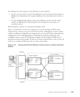
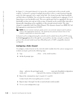
www.dell.com | support.dell.com Figure 1-6. Integrated Switch Modules Connected to Two External Switches channel client ip address 1 external network switch external network switch switch module 1 uplink ports (4) internal ports (6) switch module 2 uplink ports (4) internal ports (6) server module 1 LOM 1 ip address 1 LOM 2 ip address 2 server module 2 LOM 1 ip address 1 LOM 2 ip address 2 client ip address 2 channel To configure the static channel on integrated switch modules to two external switches (see Figure 1-6), see "Configuring a Static Channel." Configure the dynamic channel for each external switch. See "Configuring a Dynamic Channel." Using the KVM Switch The onboard KVM switch allows you to select the keyboard, video, and mouse from one server module to another. In addition, the KVM switch module can be connected to a KVM-over-IP switch so that you can monitor multiple systems in a rack. The analog rack interface port (see Figure 1-3) connects to an external KVM-over-IP switch. Figure 1-7 shows an example of how the system can be managed by connecting directly to the onboard KVM switch. 1-14 System Configuration Guide
-
 1
1 -
2
-
3
-
4
-
5
-
6
-
7
-
8
-
9
-
10
-
11
-
12
-
 13
13 -
 14
14 -
 15
15 -
 16
16 -
 17
17 -
 18
18 -
 19
19 -
 20
20 -
 21
21 -
 22
22 -
 23
23 -
24
-
25
-
26
-
27
-
28
-
29
-
30
-
31
-
32
-
33
-
34
-
35
-
36
-
37
-
38
-
39
-
40
-
41
-
42
-
43
-
44
-
45
-
46
-
47
-
48
-
49
-
50
-
51
-
52
-
53
-
54
-
55
-
56
-
57
-
58
-
59
-
60
-
61
-
62
-
63
-
64
-
65
-
66
-
67
-
68
-
69
-
70
-
71
-
72
-
73
-
74
-
75
-
76
-
77
-
78
-
79
-
80
-
81
-
82
-
83
-
84
-
85
-
86
-
87
-
88
-
89
-
90
-
91
-
92
-
93
-
94
-
95
-
96
-
97
-
98
-
99
-
100
-
101
-
102
-
103
-
104
-
105
-
106
-
107
-
108
-
109
-
110
-
111
-
112
-
113
-
114
-
115
-
116
-
117
-
118
-
119
-
120
-
121
-
122
-
123
-
124
-
125
-
126
-
127
-
128
-
129
-
130
-
131
-
132
-
133
-
134
-
135
-
136
-
137
-
138
-
139
-
140
-
141
-
142
-
143
-
144
-
145
-
146
-
147
-
148
-
149
-
150
-
151
-
152
-
153
-
154
-
155
-
156
-
157
-
158
-
159
-
160
-
161
-
162
-
163
-
164
-
165
-
166
-
167
-
168
-
169
-
170
-
171
-
172
-
173
-
174
-
175
-
176
-
177
-
178
-
179
-
180
-
181
-
182
-
183
-
184
-
185
-
186
-
187
-
188
-
189
-
190
-
191
-
192
-
193
-
194
-
195
-
196
-
197
-
198
-
199
-
200
-
201
-
202
-
203
-
204
-
205
-
206
-
207
-
208
-
209
-
210
-
211
-
212
-
213
-
214
-
215
-
216
-
217
-
218
-
219
-
220
-
221
-
222
-
223
 |
 |
