Dell PowerEdge 1655MC System Configuration Guide - Page 13
Integrating the System Into the Network - integrated switch
 |
View all Dell PowerEdge 1655MC manuals
Add to My Manuals
Save this manual to your list of manuals |
Page 13 highlights
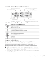
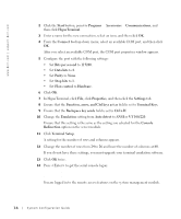
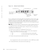
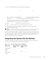
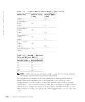
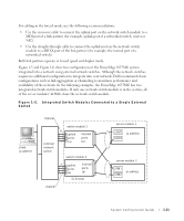
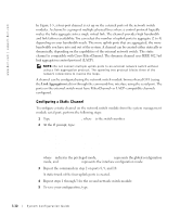
5 To set a static IP address for the network switch module, type: #config (config)#interface vlan 1 (config-if)#ip address (config-if)#exit (config) #ip default-gateway (config)#exit #copy running-config startup-config where # indicates the privileged mode, (config) represents the global configuration mode, and (config-if) represents the interface configuration mode. The network switch module can store multiple configuration files. The network switch module prompts you for a filename for the configuration. 6 Type quit or exit to logout of the serial switch console. 7 Type ~. and press to return to the management console. 8 To configure the second network switch module (if one is present), perform the previous configuration steps. NOTE: It is recommended that you change the default user name and password. For further information, see the Dell PowerEdge Integrated Switch User's Guide. After the network switch module is configured, you may use the browser-based GUI, Telnet consoles by way of the network, or continue to configure the network switch module using the serial command-line utility. See the online Dell PowerEdge Integrated Switch User's Guide for detailed information on configuration. Integrating the System Into the Network The Dell™ PowerEdge™ 1655MC is essentially a self-contained network. Table 1-2 and Table 1-3 show the mapping of the internal and external ports. Table 1-2. Internal Network Port Mapping Module Port Server module 1 LOM 1 LOM 2 Server module 2 LOM 1 Network Switch Network Switch 1 Port 2 Port 1/1 1/1 1/2 System Configuration Guide 1-9
-
 1
1 -
2
-
3
-
4
-
5
-
6
-
7
-
 8
8 -
 9
9 -
 10
10 -
 11
11 -
 12
12 -
 13
13 -
 14
14 -
 15
15 -
 16
16 -
 17
17 -
 18
18 -
19
-
20
-
21
-
22
-
23
-
24
-
25
-
26
-
27
-
28
-
29
-
30
-
31
-
32
-
33
-
34
-
35
-
36
-
37
-
38
-
39
-
40
-
41
-
42
-
43
-
44
-
45
-
46
-
47
-
48
-
49
-
50
-
51
-
52
-
53
-
54
-
55
-
56
-
57
-
58
-
59
-
60
-
61
-
62
-
63
-
64
-
65
-
66
-
67
-
68
-
69
-
70
-
71
-
72
-
73
-
74
-
75
-
76
-
77
-
78
-
79
-
80
-
81
-
82
-
83
-
84
-
85
-
86
-
87
-
88
-
89
-
90
-
91
-
92
-
93
-
94
-
95
-
96
-
97
-
98
-
99
-
100
-
101
-
102
-
103
-
104
-
105
-
106
-
107
-
108
-
109
-
110
-
111
-
112
-
113
-
114
-
115
-
116
-
117
-
118
-
119
-
120
-
121
-
122
-
123
-
124
-
125
-
126
-
127
-
128
-
129
-
130
-
131
-
132
-
133
-
134
-
135
-
136
-
137
-
138
-
139
-
140
-
141
-
142
-
143
-
144
-
145
-
146
-
147
-
148
-
149
-
150
-
151
-
152
-
153
-
154
-
155
-
156
-
157
-
158
-
159
-
160
-
161
-
162
-
163
-
164
-
165
-
166
-
167
-
168
-
169
-
170
-
171
-
172
-
173
-
174
-
175
-
176
-
177
-
178
-
179
-
180
-
181
-
182
-
183
-
184
-
185
-
186
-
187
-
188
-
189
-
190
-
191
-
192
-
193
-
194
-
195
-
196
-
197
-
198
-
199
-
200
-
201
-
202
-
203
-
204
-
205
-
206
-
207
-
208
-
209
-
210
-
211
-
212
-
213
-
214
-
215
-
216
-
217
-
218
-
219
-
220
-
221
-
222
-
223
 |
 |
